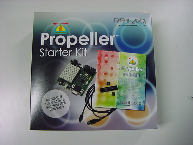
Propeller Diary (1)
Yoichi Nagashima

Saturday 9th, February 2008
Issue release date in March of "Transistor technology" to subscribe to regular only by nothing but one magazine at home. Skim as usual with [sa], take to the laboratory, detach the advertisement in one month, and to the bookshelf --- It must.. nail it down in one article.One-chip microcomputer inquiry---This (^_^;) : in what. 2/10 and 2/11 will be made a thing read at the beginning of the week by a general entrance exam because it is busy the next day for the time being.
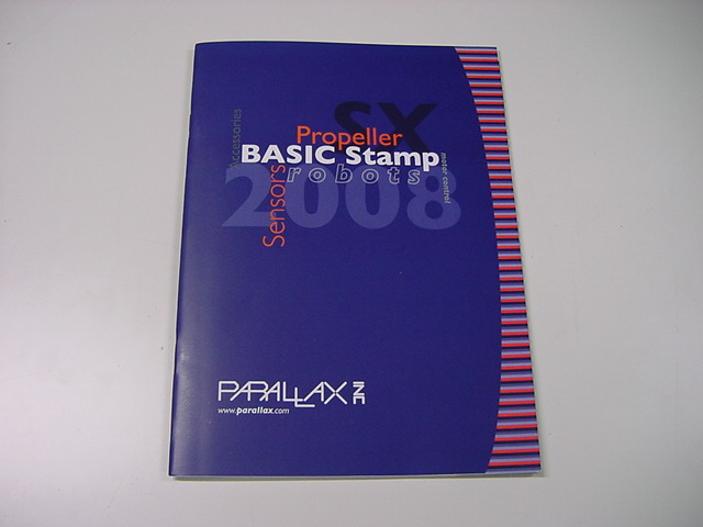
Multiprocessor microcomputer Propeller P8X32 that eight 32 bits CPU process sequentially: Masahiko KuwanoMonday 11th, February 2008
Because no obstruct enters on holiday, this article is deliberately read. This is terrible or is transformed, is even artistic, and exists. This came the inside array of eight CPU cores for the multitask, and the compulsory slice at time. It is American though does.Tuesday 12th, February 2008
It was in the article on the transistor technique. Japanese agency From Ito of ..drinking.. [sa] Propeller was developed. Parallax Co. Place where Basic Stamp was developed and turning out. Indeed.Thursday 14th, February 2008
Because it is a schedule of 2/15, 2/16, and the business trip the next day, It was in the article on the transistor technology from Propeller page, this and this ,I print them. It decided to peruse it in Shinkansen.Monday 18th, February 2008
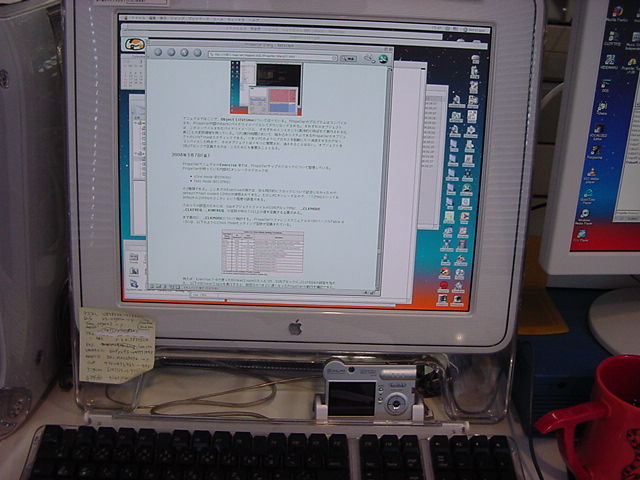
The introduction article on the transistor technology is extent in which information on the site of Propeller is translated, and the schematic diagram and the example of the reference have understood the thing that is all samples on the site (^_^;). ---However, it liked Propeller CPU. This is the heaven fine. I variously immediately ordered the basic one. When coming back from the trip to Okinawa on - the25th of the 22nd, it is a schedule of the arrival because it assumed sending out by service (For about one week) usually.Tuesday 19th, February 2008
The development tool was downloaded for the time being and installed in the Windows personal computer because it had ordered. Then I printed from Propeller page - this , this , this , this , this , this , this , this , and this . Reading actually comes hardware and. In addition, the main sample program collections were collected. It appears and the user ..very all over the world.. ..the core.. is a pattern of about 1500 people from the number of download. Propeller of about two years still(^_^;)Tuesday 26th, February 2008
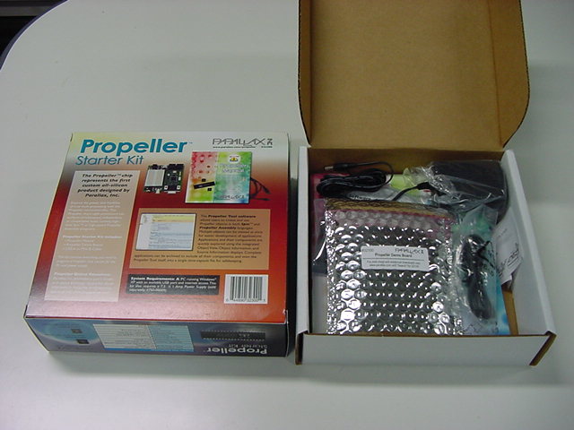
Things finally arrived on next day evening where it returned from the trip to Okinawa. The agency is also unnecessary in any age that can be bought on the Internet. As for the carriage from the United States, only in an American region, and 800 yen was taken by the tariff for 200 yen by the mail company in Japan.Wednesday 27th, February 2008
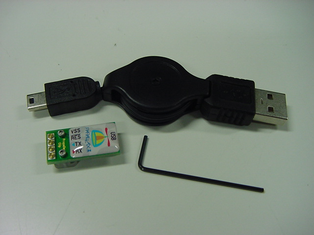
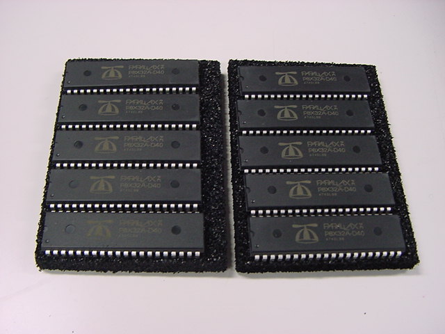
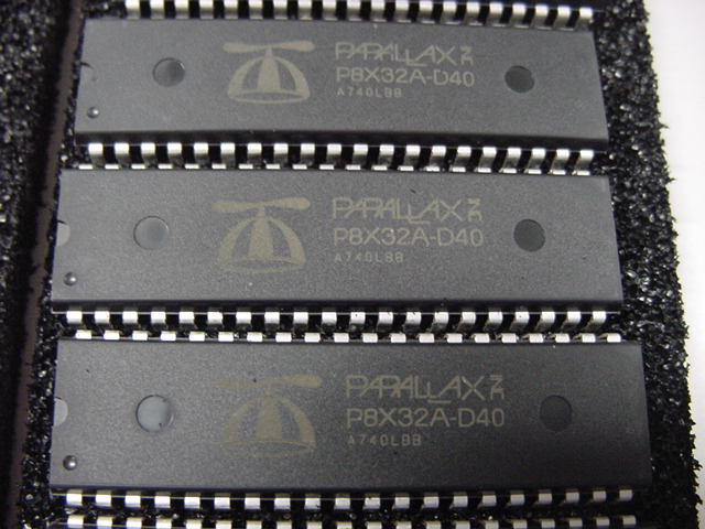
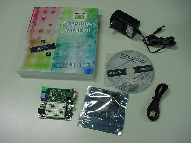
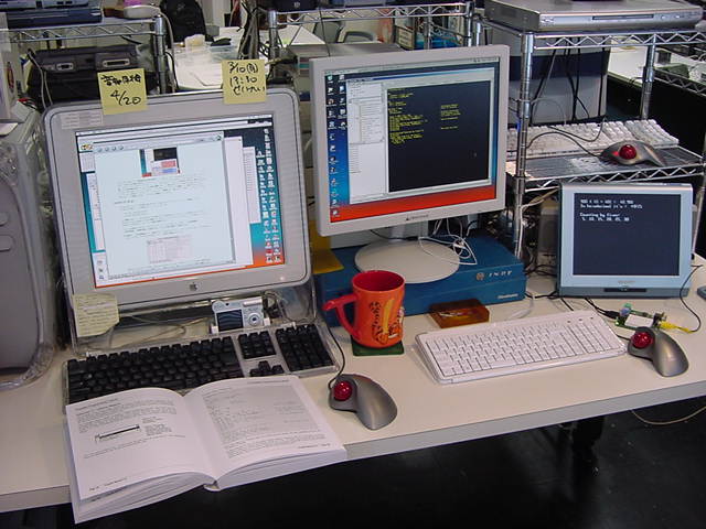
What reached from the United States was arranged. It is ..net shopping advanced country.. steady though it does.
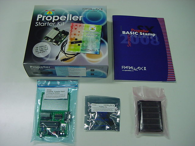


When CDROM of the appendix is copied onto HDD, it is not possible to recognize it why. Even Mac is useless. Copy CD-R was made, and, then, it read because it had recognized it in the Windows another note. However, the version of the Propeller tool was collected older than the latest of the net though there were contents from the catalog, documents of all products of this company such as BasicStamp, and WinZIP to the Acrobat leader and there was no novel one. Is even the bundle of CDROM already an unnecessary age?
Thursday 28th, February 2008
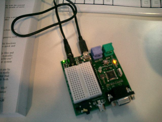
The demonstration kit was opened. LED was blinked, and it ..[ikinari].. moved when it changed to LED on the board of the port of the sample program, and it did to RAM in "Run". (^_^;)It moves neatly by that program when USB is removed after the forwarding site is made EPROM, it loads, and it forwards it and the reset start is done. This is easy [daa;] from AKI-H8 for a long time. (^_^)
Friday 29th, February 2008
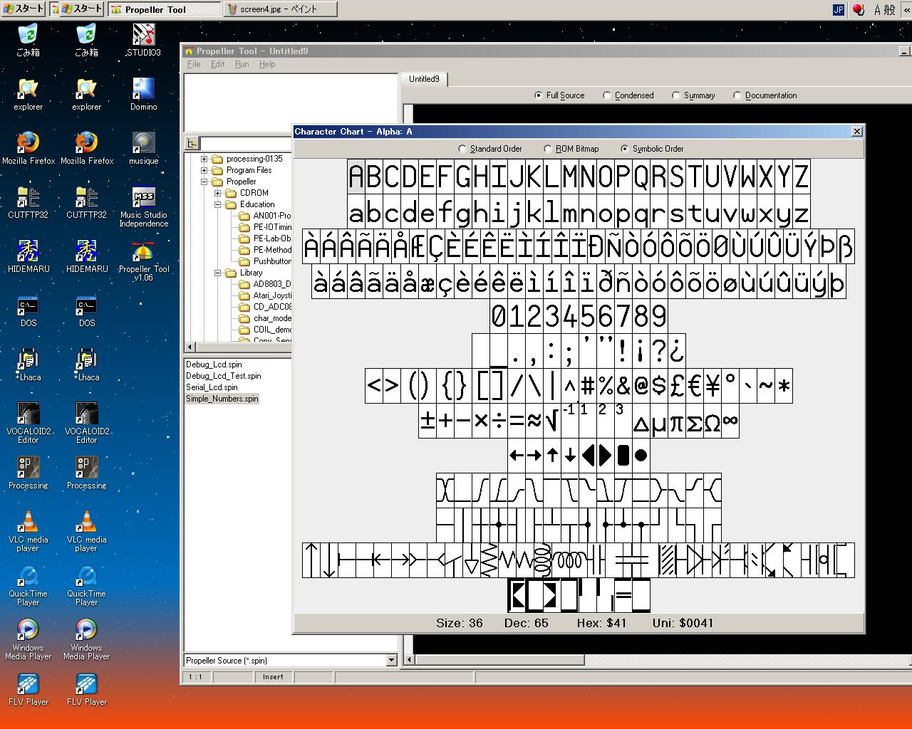
The font must come in succession and cut to anxious in the development tool of Propeller. There is no menu that switches the font though there is a menu to which the size of the text is changed.
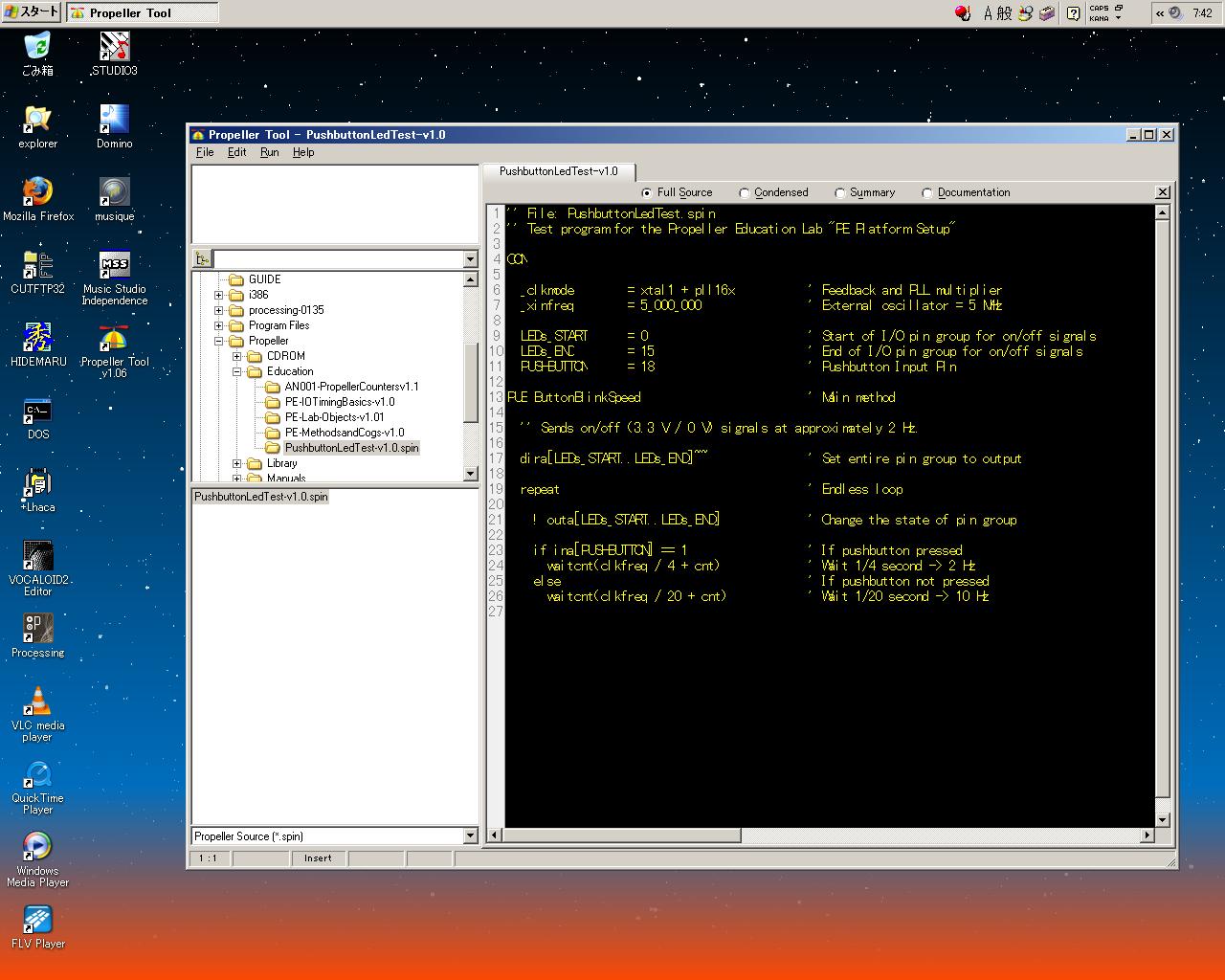
Separately opening separately in the editor is Nan [dashinaa;]. ---Thus, the mail of the question was put out to the maker and the Parallax Co. of Propeller because it was special.
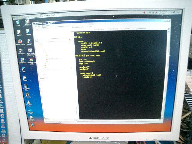
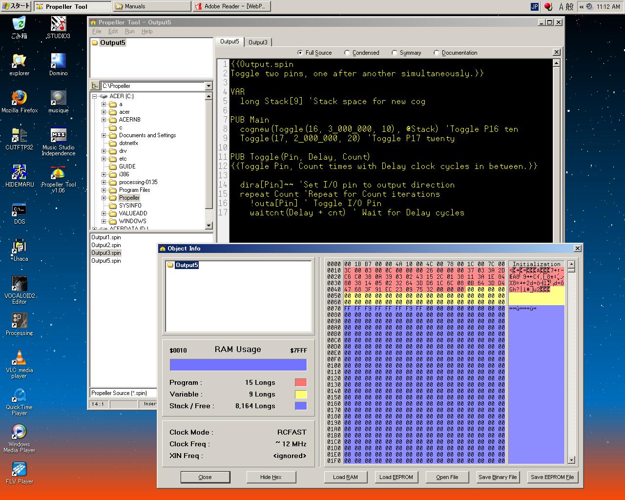
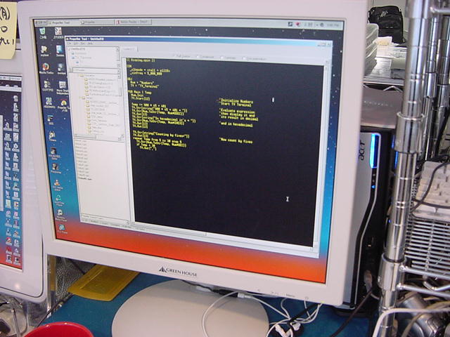
* Operating system Microsoft Windows XP Home Edition Version 2002 Service Pack 2 * PC type (desktop or laptop) Desktop Acer Incorporated AMD Athlon 64 Processor 3500+ 2.21GHz��1.94GB RAM * Software running Propeller Tool * Version number Virsion 1.06 P8X (c)2004-2008 I have just bought your Propeller chips, Starter Kit, etc. And I have just started learning. PC-Demo board connection is good, demo program is well downloaded, and test program works well ! Hardware and interface are very smart !! TROUBLE and QUESTION Please watch the attached JPEG - screenshot of my PC. I cannot read by the font of the source code coming in succession in ugliness. I discovered the function to change the text size of the area of the source code in the menu of this tool. However, I was not able to discover the function to change the font type of the text. My OS is Japanese Windows XP environment. I think that this is one of the cause of troubles. Please teach the method of changing the font of the text of the source code in this tool.---Then, it was timely or it put out and the mail of the reply came at a few minutes. (^_^;)
Yoichi Nagashima,

	That particular font is special for the Propeller tool; which is a fixed
pitch font. This isn't something that can be changed because of the format
of the Propeller Tool; it's something that is being spoken about in the
forums, but there isn't a fix for it yet but you can monitor for the latest
update from our engineers.

Parallax Forums [ Propeller ]:
http://forums.parallax.com/forums/default.aspx?f=25

Supporting Staff,

Joshua Donelson
 [ Technical Support ]
It felt admiration for the correspondence that was quite quick, and made a chitin. Because the application specifies a fixed font, it is not revokable. ---..peel.. . of ..floatage.. [-] After all ..this.., ..[kopipe].. ..round trip.. [kaa;]. open [**] round editor in another window And, there were about 5000 articles in the past when this forum was seen. It is very [daa;] when absorbing it. (^_^;)
---A few minutes ..search... solving Such information is discovered in the forum.
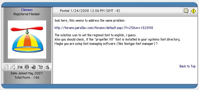

It tried immediately. "Region and language" of the control panel is changed from Japanese to English. Externals are complete change [nashi]. However, when the development setting is started, it splendidly becomes beautiful, and it solves the problem. It is FAQ, and [sasugada] . when embarrassing it. (^_^)

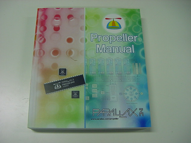
The trouble of the environment disappeared by this. It only tries variously. Propeller Manual I decided to read this and to read [naname] sequentially. Because Chapter 1 was Introduction has already been read by the printout, it passes.
Because Chapter 2 was an explanation of Propeller Tools, it read for a moment neatly. First of all, it praised oneself when this tool was made from the experience and dissatisfaction because the engineer of the Parallax Co. had used various CPU development environments up to now for 20 years or more (^_^;). In addition, not only the annotation of the code but also Document of the explanation of the program was described in the source though it was plain text as the conclusion to say nothing of the source code of CPU.
The interesting one is a font table stored in an internal mask ROM of Propeller. It is equipped with parts that can compose the schematic diagram though this is displayed by how to arrange it like the following three kinds of.
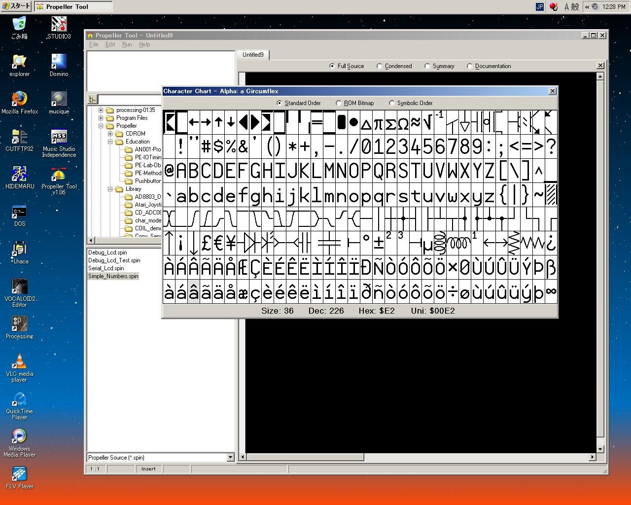
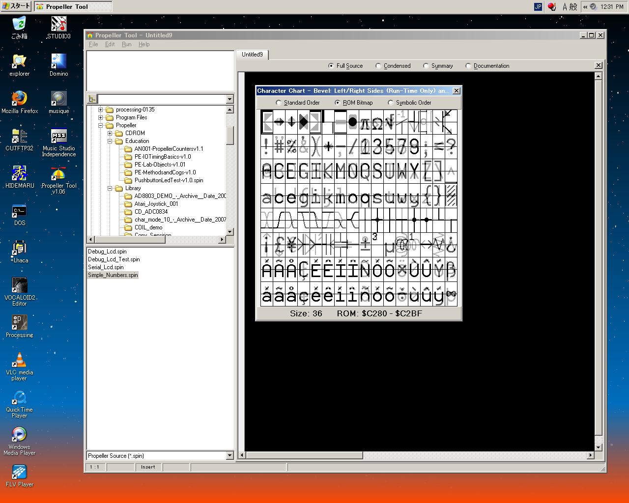
And, when the font set of this making specially is installed Propeller Tools and starts first, a usual text editor becomes available as True Type font of the computer. In a word, not only textual information but also the schematic diagram of Propeller and the peripheral circuitry was able to be described as a document that was able to be described in the source code. This is wonderful.

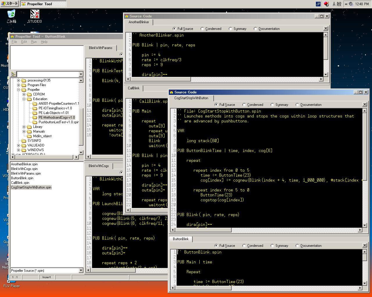
In Propeller Tools, IDE for the software development is [darou] of [maa;konnamo] splendid. It is well-made though a rough point is an expectation street even if there is no explanation. In an internal Editor sub-window (It seems to be called Editor Pane) It supports it as follows and variously as a function for the opening of two or more many sources and the comparison and the [kopi-pe-suto]. It is a function glad that the person to whom this has done the software development understands.
- The tab queues up for the time being as [tabuuindou] if it opens fast.
- When the tab is dragged in Pain, the window in the tab ..along.. divides up and down as the second screen.
- A new window in the tab opens the tab in desktop when dragging it.
As the function of the editor, it can mostly be "Good [toko] taking. " though was so far. The block specification is easy, and the short cut is abundant. It might be a point of editor where efficiency seems to go up to the experience if becoming accustomed.
Monday 3rd, March 2008
Chapter 3 is Propeller Programming Tutorial more and more, and here is a real thing. In the following Chapter 4, because Chapter 5 of the Spin language is Reference of the assembly language, about this page 60 of a thick manual is "Liver. " of Propeller.It is important that the maker who wants to spread a new CPU/system is [gu] and grip user's mind by this starter kit and the manual. At the beginning of Chapter 3, though it is natural to understand neatly and to use it The condition of thing to read skill of some programming, Chapter 1, and Chapter 2 neatly is put. It is not caught in an old concept, that is, the situation to date on the other hand, and it is requested that it want you to master the idea that Propeller is new. When it was Propeller of a quite new concept, pride and the yell ..drinking.. were felt by me.
In the development language of Propeller, two of the the high-level language of Spin object-oriented and Propeller Assembly languages suited hard are, exists together, and the program can be described. It is interpreted by the interpreter in Propeller when executing it and the token of the result that the Spin language is compiled with the tool (binary intermediate language) is executed though the assembler source is output and both united C compiler at coexistence of past C and the assembler. Moreover, operation equal with a lot of Spin languages can be described in the Propeller Assembly language. I hear that it is possible to process it like handling the serial data of 19200bps directly in the Spin language as well as the assembler though it is impossible for a moment in a past high-level language. Propeller source code (***.spin) that is called Objects can describe the Spin language and the Propeller Assembly language only in the Spin language by existing together. Though it is also possible to describe all processing in the Propeller Assembly language The Spin code is necessary though it is only at least two lines because it finally executes the program.
Because it is a development setting of object-oriented, Propeller can recycle a lot of completed objects as "Software parts". Development is given to priority in the part of multitasking at the program that is the uniting body of a lot of complex processing, and because processing is essentially distributed to eight internal CPU respectively for Propeller, it seems that the software development that it is considerably efficient and reliability is high can be done if it is possible to understand well. It is likely to turn to the robot etc. that are the sets of the job divided into the sensor and the actuator of each part. As for the inside, it seems not to have even to know anything as Object of the software parts is concrete because a certain Object file is good at the include of other Object files. Object of most significant (The project is shown) is called Top Object File.
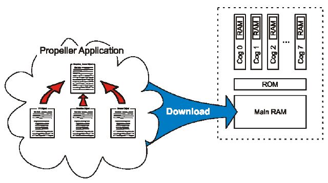
When explaining in figure of manual The program of Propeller is executed by being downloaded to common RAM the area in the Propeller chip.
Or, the program of common RAM the area in this chip is programmed to EEPROM When resetting it, Propeller begins operation of the program searching for EEPORM if the connection with the host is broken under such a condition.
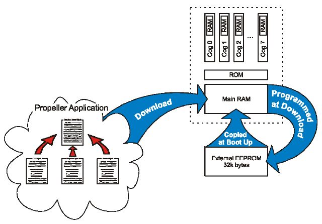
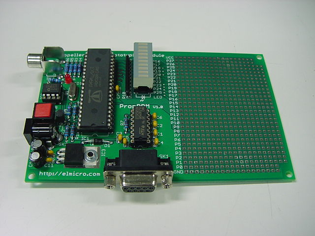
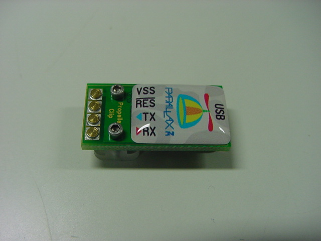
If a small USB connection adaptor named Propeller PLUG is used, at least needing it to connect host PC and Propeller will live by the following compositions. As for this, I felt sticking to to an easy development setting because it was refined further than AKI-H8 of the moon electron in autumn.
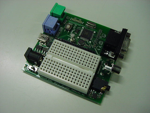
All schematic diagrams of Propeller Demo Board are this . The circuit of Propeller PLUG is the following. Of course, this circuit is recorded in Propeller Demo Board, too.
This is actually mounted on Propeller Demo Board that exists in the starter kit though the following external circuits are requested here in the tutorial. In a word, it puts it in the tutorial without doing anything hard in the starter kit. It will work suddenly both hardness and software when it touches new CPU the moon electron is to do by here in autumn though was one wall here.
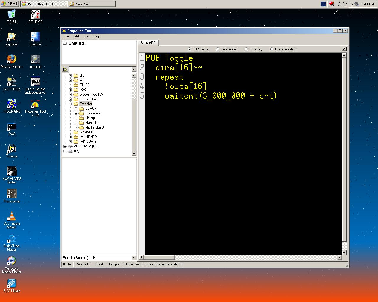
Well, it became the page of Exercise 1. The following can ..Propeller Tool.. be driven by not saying anything, and becoming silent. I hear, it was "Write the line of PUB without opening it from the left end" and "Note the indent because it is important" however. Because changing line, the indent, and space were arbitrary in C, Java, and HTML, it is puzzled for a moment. If it is a person to whom a cervine programming has been done of what, the operation of this program will be able to be expected almost. The purpose of making to PUB and the entire capital letter is to understand in the tutorial of the manual, and it is said that capital letters and small letters will not be distinguished. It was relieved to this for a moment.
The following dialogs appeared for a brief flash, red, on Propeller Demo Board blue LED blinked, and LED of P16 came to blink splendidly when assuming Compile Current and Load RAM from Run here by F10 or the menu.

The processing that Propeller Tool did in this moment is the following.
- The source code was compiled and it made it to the Propeller application.
- It searched for the Propeller chip via USB.
- This program was forwarded to internal RAM of the Propeller chip.
- This program was executed specifying reset to the Propeller chip.
- The output of P16 repeated blinking by the program.
Here, this program has not run any longer when the reset button on Propeller Demo Board is pushed. Because contents of RAM disappear by reset. Finally, when not F10 but F11 was pushed, the dialog was displayed longer this time, and it became the same operation however. And, this ran again when the reset button on Propeller Demo Board was pushed. From Run to the reason for F11 is that processing named Compile Current and Load EPROM menu in this difference What is it host PC it after it resets it because it doesn't communicate any longer ..writing this program after it forwards it in addition in external EEPROM.. to RAM?, Next..EEPROM..search..this..program..execute. Though AKI-H8 etc. are debuggings and have worry a little in hundreds of time thousands of times and EEPROM, because when the bug can be taken by writing it even times how many in internal RAM when developing, it is a function in EEPROM
At last, a detailed explanation of the following programs continues in the tutorial in the place in which it actually moved.
PUB Toggle
	dira[16]~~
	repeat
		!outa[16]
		waitcnt(3_000_000 + cnt)
It is a definition. The term named PUB of public is indispensable to all Objects though Toggle is an arbitrary name.
Direction of port 16(direction) is set to the output port by "dira16~~ of the second line". The symbol named DIRA sets the direction register whether 32 ports from P0 to P31 are input or output it. Because the operator of "~~" is Post-Set operation, it is equivalent to "dira 16 := 1".
The block after that is infinitely looped by "repeat" of the third line. This REPEAT is a reservation symbol. Will this be object-oriented though it is indescribably unstable in the sense of C not to specify the end of the loop?(^_^;)
The output status of port 16 is reversed by "outa16" of the fourth line. The toggle operation is achieved. "!" of the bit inverting is an operator also in other languages with often. The symbol named OUTA sets the value of the output register of the port set to the output to 32 ports from P0 to P31.
"waitcnt(3_000_000 + cnt)" in the last line on a page is wait at three million clock cycle. The WAITCNT symbol is "Wait of the system counter", and the CNT symbol (present) is a value of the system counter register. Then, this instruction becomes a thing "It is wait in the value of a present system counter until becoming three million count value in which it adds". If this three million is counted because the system clock of the Propeller chip of default is 12MHz, it becomes about 1/4 seconds.
"Attention of the tidy recognition of the indent in Propeller Tool" and [nen;o] are done as a summary at the end. The note of IF or CASE or REPEAT is necessary for recognition by the indent. Also in space and the tab, "One space or more" seems to be standards of the indent in the minimum. It would be better not to make space exist together to the tab in the indent to avoid confusing.
Tuesday 4th, March 2008
The following topic is Cogs (Processors) following summary (Quick Review) of Ex.1 There are eight independent Cog (cogwheel) in Propeller, and this is the maximum feature. Each Cog can be possible independent operation and cooperated operation, and switch this mode to the difference while executing it. By the way..sample..program..our..which..conscious.Actually, Cog(0) of 8 pieces is a processor used with Boot-Up of default. When the communication with PC is not detected, an internal boot loader is forwarded with built-in Propeller ROM to internal RAM of Cog(0) when the power supply enters Propeller as follows. And, with the boot loader executed with Cog(0), External..EEPROM..program..inside..main..common..RAM..forward. Afterwards, the boot loader loads the Spin interpreter with built-in Propeller ROM into internal RAM of Cog(0) in the superscription. And, the Spin interpreter of Cog(0) executes the program loaded into main (commonness) RAM in Propeller. The other any seven Cog is not done and exists in the stand-by state between here.
Well, it continuously became the page of Exercise 2. The theme is Constants. The program was as follows.
CON
	Pin = 16
	Delay = 3_000_000

PUB Toggle
	dira[Pin]~~
	repeat
		!outa[Pin]
		waitcnt(Delay + cnt)
The time of the I/O port number that appears in two or more places or DeLay can be efficiently specified by defining it as a constant by using the constant though operation is the same as the one of Ex.1. To use two or more Cogs properly, this will become indispensable.
The CON block that appeared here is a reserved word for the global constant. Pin that appears as a symbol or any Delay can be defined if not coming in succession as the reserved word. If the symbol named Pin or Delay is used by this program in other places, the value becomes 16 or three million as long as not rewritten. Because "Comma" that man daily uses to show the figure of a big digit in the grammar cannot be used, "_" can be used to delimit three digits. This is disregarded as a figure.
There is the one like other sequenteses though the reserved word of the block specification that appears here is PUB and CON. Private method and DAT are the data blocks. the reference and PRI of the object the variable and ..VAR.. ..global.. OBJ
CON Global Constant Block. Defines symbolic constants that can be used anywhere within the object (and in some cases outside the object) wherever numeric values are allowed. VAR Global Variable Block. Defines symbolic variables that can be used anywhere within the object wherever variables are allowed. OBJ Object Reference Block. Defines symbolic references to other existing objects. These are used to access those objects and the methods and constants within them. PUB Public Method Block. Public methods are code routines that are accessible both inside and outside the object. Public routines provide the interface to the object; the way methods outside of the object interact with the object. There must be at least one PUB declaration in every object. PRI Private Method Block. Private methods are code routines that are accessible only inside the object. Since they are not visible from the outside, they provide a level of encapsulation to protect critical elements within the object and help maintain the integrity of the object��s purpose. DAT Data Block. Defines data tables, memory buffers, and Propeller Assembly code. The data block��s data can be assigned symbolic names and can be accessed via Spin code and assembly code.It is necessary to have at least one or more PUB blocks as Propeller target (program). OBJ and DAT can be put only once with CON and VAR though all blocks may be put in what order, and many PUB and the PRI block can be put. Moreover, there is a special meaning in PUB that is most first when two or more PUB blocks are put, and it becomes the start point of the Propeller program. It might be the one like main() of C language. In the edit display of Propeller Tool of default, these blocks can be distinguished by the difference of the background color.
The following are pages of Exercise 3. The theme is a comment (annotation). The program is a sequentes, and contents are quite the same.
{{Output.spin
Toggles Pin with Delay clock cycles of high/low time.}}

CON
	Pin = 16 				{ I/O pin to toggle on/off }
	Delay = 3_000_000 		{ On/Off Delay, in clock cycles}

PUB Toggle
''Toggle Pin forever
{Toggles I/O pin given by Pin and waits Delay system clock cycles
in between each toggle.}

	dira[Pin]~~ 			'Set I/O pin to output direction
	repeat 					'Repeat following endlessly
		!outa[Pin] 			' Toggle I/O Pin
		waitcnt(Delay + cnt) 	' Wait for Delay cycles
In short, the comment sign is prepared as follows in every 2*2=4 kinds like a single line, the multiline, the code part, and the document part, etc.
- If the apostrophe is 1 piece, the code part of a single line is annotated.
- If apostrophes are 2 pieces, the document part of a single line is annotated.
- The code part of the multiline is annotated if inside parentheses are one pair.
- The document part of the multiline is annotated if inside parentheses are two pairs.
It continuously advances to Exercise 4. The argument is passed to the method, and the loop of limited times seems to appear, and, at last, to have programmed it here.
PUB Main
	Toggle(16, 3_000_000, 10)
	Toggle(17, 2_000_000, 20)

PUB Toggle(Pin, Delay, Count)
	dira[Pin]~~
	repeat Count
		!outa[Pin]
		waitcnt(Delay + cnt)
In this example, Main that is PUB that appears first becomes the entire main program. And, the symbol named Pin, Delay, and Count is assumed to be an argument, the port is specified with Pin respectively, it blinks at intervals of Delay, and the repetition is ended by the frequency of Count in the method named Toggle. One method of passing thoroughly can be specified by changing the parameter from the call side. The constant given by each symbol becomes not the word it but long (width of four bytes in the width of 32 bits). Having the parameter of frequency as the REPEAT instruction repeats Because you can not separately check the variable of the loop counter, it is a function for a moment glad.
Wednesday 5th, March 2008
Exercise 5 and the topic are Parallel Processing only of Propeller more and more. In the program of Exercise 4, "Toggle(17, 2_000_000, 20)" was executed as LED of port 16 was executed unpalatable "Toggle(16, 3_000_000, 10)" and blinked five times, and continued and LED of port 17 blinked ten times. This is a serial processing, that is, serial processing.It is necessary to achieve the timesharing parallel processing in blinking with usual CPU according to two LED separate respectively timing as ..interrupt.. software multitask. However, because the I/O port can be exclusively connected with each Cog in Propeller The multitask that blinks LED of each port can be easily achieved by an easy following programs.
{{Output.spin Toggle two pins, one after another simultaneously.}} VAR long Stack[9] 'Stack space for new cog PUB Main cognew(Toggle(16, 3_000_000, 10), @Stack) 'Toggle P16 ten�� Toggle(17, 2_000_000, 20) 'Toggle P17 twenty�� PUB Toggle(Pin, Delay, Count) {{Toggle Pin, Count times with Delay clock cycles in between.}} dira[Pin]~~ 'Set I/O pin to output direction repeat Count 'Repeat for Count iterations !outa[Pin] 'Toggle I/O Pin waitcnt(Delay + cnt) 'Wait for Delay cyclesIn this program, two Cog is started for the blinking processing of each LED. It is VAR block that appeared newly, and secures the variable of the symbol named Stack of 9Longs (Because it is neither Byte, nor Word, and width of 32 bits, it is unit named Long) for the time being. This is used by the Main method.
A new command of "COGNEW" appeared in the PUB block where the name of Main had been put most first. It is a code of Spin or the Propeller assembler that COGNEW specifies for the first parameter, and is a method named Toggle here. COGNEW specifies for the second parameter "@Stack". The address of RAM that Cog newly started uses as running stack space is shown. "@" returns the stack real address of the symbol following it. It is certainly understood that 9Longs is secured on the Object Info screen of Propeller Tool though it is assumed that it will introduce it later when attaching why securing the stack of 9Longs (36 bytes) here. It seems to change according to the executed Spin code because the return address, the return value, and the middle data, etc. enter as temporary information for the stack.
Cog(0) first executes "cognew(Toggle(16, 3_000_000, 10), @Stack)" when this program is executed, and blinking LED of P16 begins on execution "Toggle(16, 3_000_000, 10)" the following Cog(1). this Blinking LED of P17 begins because Cog(0) continuously executes "Toggle(17, 2_000_000, 20)" as my program. These operation progresses at the same time as a parallel processing. Because the code already is not described as follows ..that.. when the processing of Toggle ends by the REPEAT frequency ..Cog(1) and.., operation is ended and it stops. Because the following code doesn't exist any longer, it stops though Cog(0) returns to Main when the processing of Toggle ends by the REPEAT frequency. Because it is unrelated which ends early. This mechanism is explained as shown in the following figures.
Spin in the development setting has the concept of object-oriented though Propeller is hardware multitask CPU. In Exercise 6, the programming of object-oriented finally becomes a leading part. The following sample "Output.spin" is Start and an object of which everything changed from Main from which everything doesn't operate anything in this as for the symbol.
{{ Output.spin }}

VAR
	long Stack[9] 		'Stack space for new cog

PUB Start(Pin, Delay, Count)
{{Start new toggling process in a new cog.}}

	cognew(Toggle(Pin, Delay, Count), @Stack)

PUB Toggle(Pin, Delay, Count)
{{Toggle Pin, Count times with Delay clock cycles in between.}}

	dira[Pin]~~ 		'Set I/O pin to output direction
	repeat Count 		'Repeat for Count iterations
		!outa[Pin] 		'Toggle I/O Pin
		waitcnt(Delay + cnt) 		'Wait for Delay cycles
The program of new Cog is started when the method named Start is called, and anything doesn't occur to this because the argument is not passed in this though it is an object. This Output.spin is first put, and Blinker1.spin that calls the Start method and the Toggle method from Main as follows is made about an actual program. The name of "Output.spin" defined here becomes important because it becomes the cooperation of two or more programs (reference relationship).
{{ Blinker1.spin }}

OBJ
	LED : "Output"

PUB Main
	LED.Start(16, 3_000_000, 10)
	LED.Toggle(17, 2_000_000, 20)
Quite the same operation as Exercise 5 can be achieved by compiling this Blinker1.spin and loading it into RAM. "LED :"Output"" of the OBJ block that appeared newly means the method in outside source program Output.spin is referred from Main by the symbol of "LED". Because such a succession relation is expressed by the dot as well as Java and ActionScript, the Start method in Output.spin is called by "LED.Start(16, 3_000_000, 10)" and the Toggle method in Output.spin is called by "LED.Toggle(17, 2_000_000, 20)". This how of "object.method" to call it is exactly a style of object-oriented.
When the program of the structure to refer to the object is compiled like this, the relation is displayed in the window on the left of Propeller Tool as follows. Because this is updated only when the program compilation succeeds, it is important to check here when developing.
The distinction Top Object is any in the opening at the same time and the development of two or more objects becomes important. Because Output.spin is not Top in this example when specifying, "This Current source is compiled" with F10 when the tab in the editor is in not Blinker1.spin but Output.spin, nothing is executed as a result. It is also profitable to acquire manners of specifying Object that exists in Top specifying it to avoid such confusion by "Top Object File" of the menu, and choosing "Compilation from Top" of F11. It is not necessary to do Open, and moreover, a lower tier and a straight line object group are compiled automatically if it is referred when compiling from Top, and compose as a whole one program of Propeller Tool.
Thursday 6th, March 2008
It was not complete "Parallel" processing though the relation between the parallel processing and object-oriented of Cogs of Exercise 6 was certainly a multitask. Because there is domination in Cog(0), and the relation that the program of Cog(0) called the program of another Cog(1) to the end by chance by the COGNEW command. In Exercise 7, it develops so that two or more objects may tie to two or more Cogs more generally.First of all, Output.spin is enhanced as follows. The Stop method of stopping ..Active.. process is installed. Moreover, an infinite loop can be achieved as a parameter of the Toggle method. Because the check on whether the process is starting now is necessary to process it in Stop, the Active method for this is newly established.
{{ Output.spin }} VAR long Stack[9] 'Stack space for new cog byte Cog 'Hold ID of cog in use, if any PUB Start(Pin, Delay, Count): Success {{Start new blinking process in new cog; return TRUE if successful}} Stop Success := (Cog := cognew(Toggle(Pin, Delay, Count), @Stack) + 1) PUB Stop {{Stop toggling process, if any.}} if Cog cogstop(Cog~ - 1) PUB Active: YesNo {{Return TRUE if process is active, FALSE otherwise.}} YesNo := Cog > 0 PUB Toggle(Pin, Delay, Count) {{Toggle Pin, Count times with Delay clock cycles in between. If Count = 0, toggle Pin forever.}} dira[Pin]~~ 'Set I/O pin to output�� repeat 'Repeat the following !outa[Pin] 'Toggle I/O Pin waitcnt(Delay + cnt) 'Wait for Delay cycles while Count := --Count #> -1 'While not 0 (make min -1) Cog~ 'Clear Cog ID variableThe variable of "Cog" of bite-sized was newly first defined in VAR block. This storage-pursues ID of Cog started by Start method It is used as global variable in both Stack and Cog defined in VAR block PUB in the Output object and the PRI block. In a word, when each referring, other methods obtain the new value when this global variable is updated by a certain method.
In the Start method, the symbol named Success was continued to the symbol definition part of the method of defining (Pin, Delay, Count) and the argument by the colon, and it was described "PUB Start(Pin, Delay, Count): Success". This is to mean the result whether the start processing succeeded is defined as return value Success. The Start method doesn't necessarily succeed even whenever called because it limits the number of CPU of limited of 8 pieces in Propeller. Then, the boolean value such as standard TRUE and FALSE will enter for return value Success. By the way, PUB and the PRI method return a long value (four bytes) respectively always even if not defined here. In a word, the value named Success defined here :. It becomes the alias of the variable of the return value RESULT defined in the method by default.
The code of two lines queues up in the Start method. It is stopped if there is a process that is first called the Stop method, exists, and executed. After stopping this without fail, this starts new process without separately separately doing Stop from outside object if only this Start method is called, and there is process that exists in prior New Cog is started when there is no process in prior. The variable in the workspace defined as Stack for the start of other Cog in the past is overwrited for this start.
It is the second line of this Start method here because it is essential first. A complex following lines will be firmly seen for the understanding of Propeller Tool.
Success := (Cog := cognew(Toggle(Pin, Delay, Count), @Stack) + 1) If the pair is confirmed from the inside, the relation of parentheses is comprehensible. Three parameters: First of all, method Toggle of specifying Pin, Delay, and Count is on the inside.
Success := (Cog := cognew(Toggle(Pin, Delay, Count), @Stack) + 1) As for Toggle, starting is this COGNEW command in new Cog with the specification of stack area "@Stack".
Success := (Cog := cognew(Toggle(Pin, Delay, Count), @Stack) + 1) When Cog ID from 0 internally defined to 7 is returned when succeeding in starting new Cog, and it fails, this COGNEW command returns the value of -1. The substitution operator defined by Propeller is ":=" though it is often "=" in other languages. As a result, doing to the return value by +1, and substituting it for Cog ID variable Cog defined in VAR block are the following.
Success := (Cog := cognew(Toggle(Pin, Delay, Count), @Stack) + 1) This value is as follows.
It is a variable that can be stopped by specifying Cog from this value if there is a necessity. This value is finally substituted for return value Success of the method.
- Value from 1 to 8 when succeeding
- 0 when failing
Success := (Cog := cognew(Toggle(Pin, Delay, Count), @Stack) + 1) FALSE is 0 in the Spin language in the value of the boolean accurately, and TRUE is -1 though return value Success of Start was assumed to be Boolean. However, it ..boolean of the result actually.. doesn't contradict the result in which 0 if ..(1-8).. failing excluding 0 if succeeding because +1 was done here because the [konpea] operation judges TRUE FALSE and non-zero 0 when the comparison operation is done.
In a complex like this statement, ..parentheses.. emphasis the display where the hierarchy is included corresponding to the position in which the cursor was put is done on the editor screen of Propeller Tool.
The Stop method is a statement of only two lines following the Start method. The meaning of the line of "if Cog" executes the following line when variable Cog is TRUE (When it is non-zero), and is [dearu]. Because it is Cog number from 1 to 8, and the value of variable Cog is 0 when failing if it succeeds in starting the process (+1 was done by internal Cog ID), it doesn't contradict such a boolean judgment.
The continuing COGSTOP command : in the one corresponding to the COGNEW command. The meaning of "cogstop(Cog~- 1)" executed only when agreeing with the condition judgment of IF It is a thing of "Cog~" after "cogstop(Cog-1)". Because the number of Cog is done to +1 0-7 of internal ID, -1 is done here, it returns, and the COGSTOP command is executed. After it executes it by the one that becomes operator "~~" (post set) that has already come out and a pair, 0 clearing of operator "~" (post clearness) of the variable. As a result, Cog of specified ID is stopped, and the variable Cog becomes 0, too.
In the Active method of continuation, the annotation explains everything. The meaning of "YesNo := Cog > 0" is "Return TRUE if process is active, FALSE otherwise". Symbol ">" is an operator that returns the result of the comparison operation. This boolean result returns and it is substituted for variable YesNo defined as a value.
In the last Toggle method, it was more little than Exercise before and the significant alteration joined. The line of the last "Cog~" is the most important. In a current Toggle method, then, when the processing of Cog ends though Cog stops With this, ID allocated in started Cog cannot judge whether to be able to recycle the Start or Active method as it is. Then, the allocation of Cog becomes possible again newly because it ends clearing the Cog variable from me by the place where the blinking processing was ended at the end of the Toggle method.
Another important improvement of the Toggle method is achievement of "Infinite loop". Here, the last tricky statement "while Count :=--Count #>-1" is important. This is a part of the syntax of not single but "repeat..while". It was the one that processing was described as follows as "repeat Count" in a past example, and only the number of Count repeated processing. It is a structure of making it only repeat here, enclosing the statement of processing, and receiving it with while at the end. If the boolean condition following while is TRUE, this loop is repeated. To loop infinitely, the condition "The value of called Count is 0" was set.
The focus here became the condition of repeat..while "Count :=--Count #>-1". "--" is Pre-Decrement operator as a new operator as well as Java etc. In a word, the condition judgment starts after doing the variable first of all -1. And, unfamiliar "#>" is an operator named Limit Minimum. This is the one "If the left sides are larger than the right side, the left side is returned" and "Otherwise, the right side is returned". This result enters Count by substitution operator ":=", and the boolean judgment result becomes the condition of while.
For instance, the value becomes one by "--Count", the value is returned on the condition of this.. "#>-1", and this is substituted for Count in the first repeat if called as Count=2. The value of Count is decreased in a word, it becomes TRUE because this is non-zero, and, in addition, repeat continues. The value becomes 0 by "--Count" the second times that become Count=1 and were called, the value is returned on the condition of "#>-1" as for this, and 0 is substituted for Count. Then, it goes to the termination of becoming FALSE because the boolean judgment is zero, slipping out this repeat loop, and liberating Cog. If the value of Count is one or more, all loops become "Only the value of Count is repeated" because it is similar.
It becomes one, and and, the value of one is returned, and this is substituted for Count in the first repeat - according to the condition of this.. "#>-1" if called from the beginning this method as Count=0 ..value.. - according to "--Count". Then, it becomes TRUE because the value of Count is non-zero, and, in addition, repeat continues. It becomes two, and the value of one is returned, and this is substituted for Count since the second times - according to the condition of "#>-1" ..value.. - according to "--Count". Then, it becomes TRUE because the value of Count is non-zero, and, in addition, repeat continues. In a word, it becomes an infinite loop with -1 for a long time entered in this case for Count.
New code Blinker2.spin in which this is called is quite defined in Exercise 8 in the place where Output.spin that became a very simple code by tricky [ni] and the favor was able to be prepared.
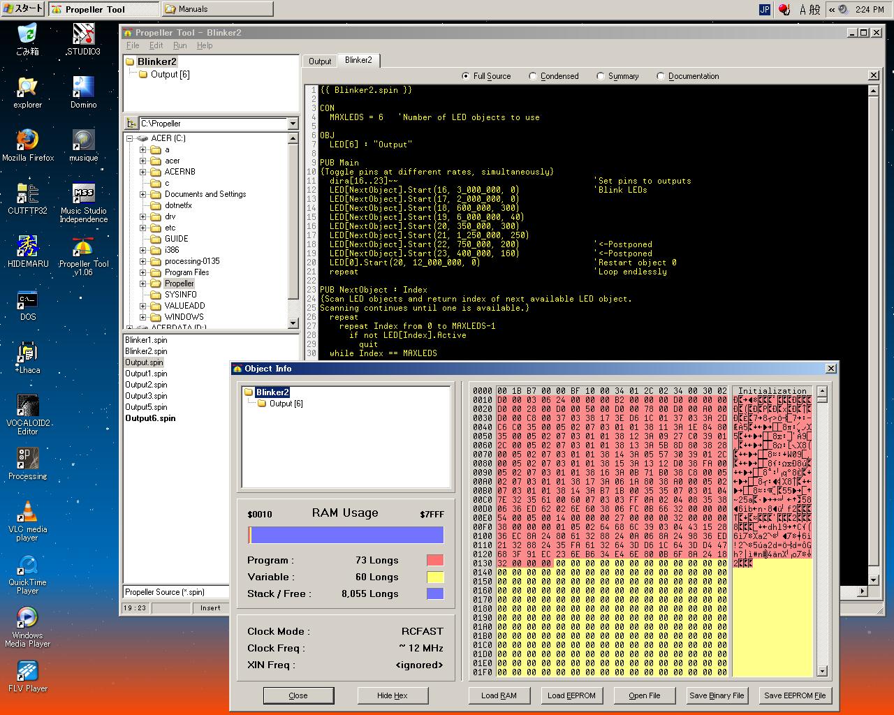
{{ Blinker2.spin }}

CON
	MAXLEDS = 6 	'Number of LED objects to use

OBJ
	LED[6] : "Output"

PUB Main
{Toggle pins at different rates, simultaneously}
	dira[16..23]~~ 				'Set pins to outputs
	LED[NextObject].Start(16, 3_000_000, 0) 	'Blink LEDs
	LED[NextObject].Start(17, 2_000_000, 0)
	LED[NextObject].Start(18, 600_000, 300)
	LED[NextObject].Start(19, 6_000_000, 40)
	LED[NextObject].Start(20, 350_000, 300)
	LED[NextObject].Start(21, 1_250_000, 250)
	LED[NextObject].Start(22, 750_000, 200) 	'<-Postponed
	LED[NextObject].Start(23, 400_000, 160) 	'<-Postponed
	LED[0].Start(20, 12_000_000, 0) 	'Restart object 0
	repeat 					'Loop endlessly

PUB NextObject : Index
{Scan LED objects and return index of next available LED object. Scanning continues until one is available.}
	repeat
		repeat Index from 0 to MAXLEDS-1
			if not LED[Index].Active
				quit
	while Index == MAXLEDS
This was compiled and it became a board with complex following behavior when forwarded-executing it. Decipherment-understanding this becomes the target of this Exercise 8.
- Six LED blinked complexly respectively according to distinct timing.
- As for P20, blinking was stopped, and P22 began blinking about eight seconds later.
- In addition, after a few seconds, P18 stopped blinking, and began blinking by P23.
- Afterwards, the interval of blinking has changed though P16 stops blinking, and began blinking by P20.
- Finally, only P17 and P20 kept blinking for a long time.
The constant is first defined for the time being in the CON block as "MAXLEDS = 6". The Output object array named "LED 6"Output"" and LED was defined in the continuing OBJ block. The purpose of this is to execute six independence and parallel processes.
It is defined in the output pin bringing the I/O pin from 16 pins to 23 pins together, "dira16..23~~opening of Main method". < can ..b>INA.. be used for the I/O register as a command that can be defined bringing two or more pins together like this b>OUTA b>DIRA. Confusion should consent from 18 pins to 23 pins as another is lit mutually even if it blinks independently because it is.
From the following line to the main program parts of this sample 8 lines such as "LED NextObject . ..Start(16, 3_000_000, 0).. " that queue up This is the one returning it searching for Cog that can be started as follows though the NextObject method is described later. The first six lines are executed at once, and six Cog starts from each port and LED starts the blinking operation because it has limited six LED used here. The first two operates by an infinite loop because the value of Count is 0. Four of the remainder loops respectively only the specification of Count and ends. Then, because the period without Cog that ends the process and has become empty doesn't return from the NextObject method to the statement of the seventh line, it is made to wait making no progress. The LED.Start processing is executed here, and it is executed with the seventh line and the 8th line because the process ends when time like the multiplication result of the value of Delay and the value of Count passes, and it returns with the Cog number that becomes empty. Because the last ninth line is not NextObject and specifies "index 0" directly It is started first and here is started ending the process of P16 that was an infinite loop. Operation becomes an infinite loop (standby) because there is a statement of "repeat" at the end while having reached here. The I/O pin of Cog that ends the process becomes the input pin of the initial state, and the pin and Cog of an infinite loop of the LED output continue the state.
"NextObject" The method processes it, that is, return searching until "Next, number of the LED object that can be used" is found by using the Active method of the Output object inside. First of all, the outside following end among repeat that was the nest when variable Index that is the return value is compared here with MAXLEDS that six after it executes it internally, and it differs repeating repeat as long as it is equal (Return to the call origin in Index as a return value).
And, another repeat of the following is done in the inner loop.repeat repeat Index from 0 to MAXLEDS-1 if not LED[Index].Active quit while Index == MAXLEDSVariable Index is a loop that the increment is done from 0, and the inside is executed afterwards, and Index repeats five in "MAXLEDS-1", that is, here to this. "not LED Index . Active" that was called here is LED Index specified with Index . QUIT command that is contents of IF is executed if the result of Active is received, and there is LED object that is not Active from "Return TRUE if process is active, FALSE otherwise". Processing is ended from an inside repeat loop because QUIT is the one escaping from the repeat loop only by one hierarchy and it slips out.repeatrepeat Index from 0 to MAXLEDS-1 if not LED[Index].Active quit while Index == MAXLEDSIndex becomes six that the increment is done further, comes off from the condition of inside repeat loop, and returns to outside repeat if the LED object that is not corresponding Active exists. Then, contents of this repeat loop are repeated from the beginning again because it agrees to the while condition of outside repeat. In a word, it doesn't return from this method in not being found for Cog that becomes empty to the call origin.
The loop of the outside ends, it calls, and the value of Index that went out of an inside repeat loop with QUIT returns to former method in this Index as a return value because it is smaller than MEXLEDS when it becomes a hit to the LED object that is not Active while sequentially looking for.
Here, when the usage condition of RAM area is seen with Object Info of Propeller Tool, the Program area is 73Longs, and not current 10Longs but 60Longs is used as for the Variable area as follows.
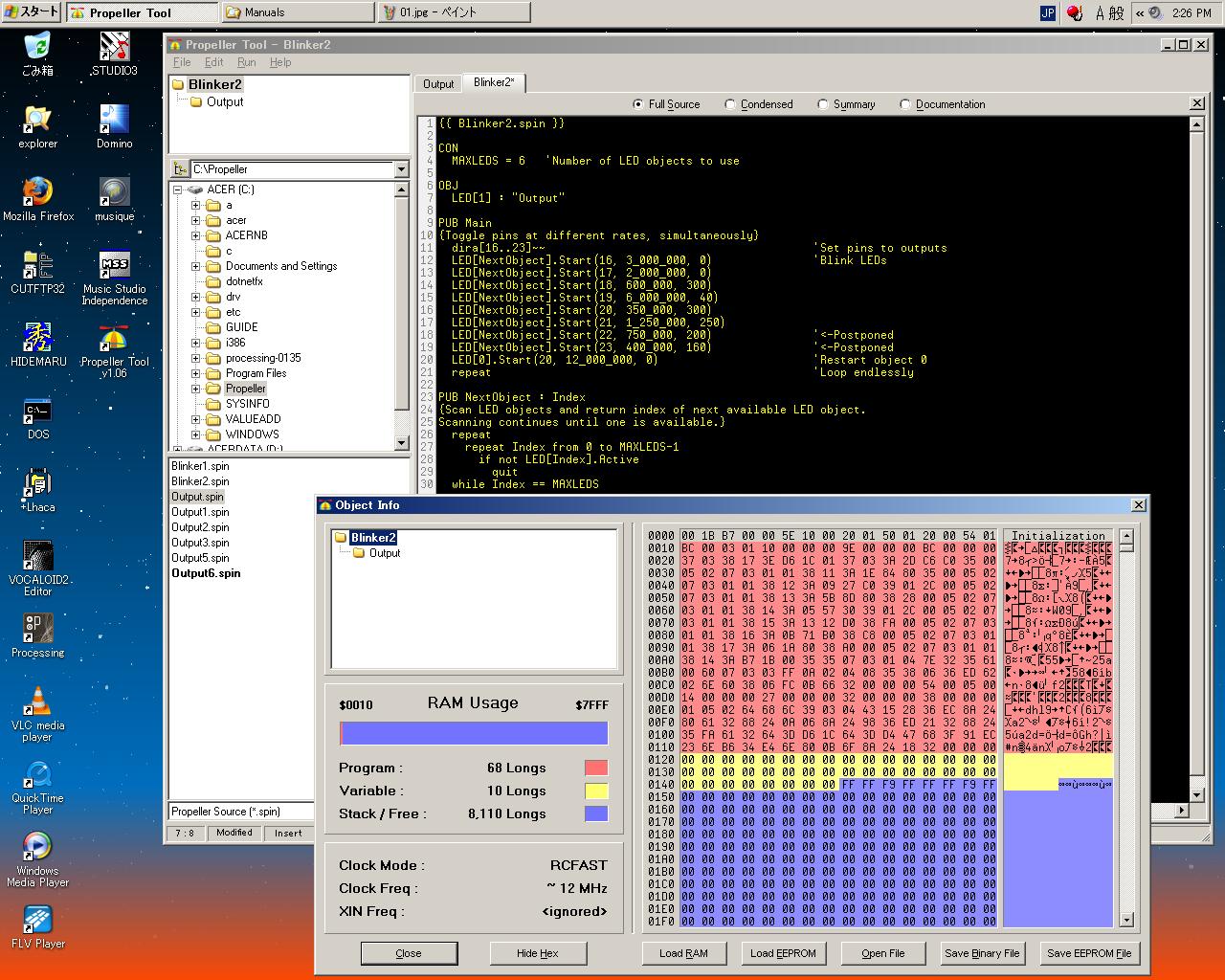
Then, when it changed, the compilation loading was done similarly, "LED 1"Output"", and the usage condition of RAM area was seen with Object Info, the Program area was 68Longs, and the Variable area .."LED 6"Output"" of the source.. became 10Longs (one byte (9Longs and Cog of Stack)) as follows. In a word, it had only one part of the code in the memory together in Propeller of object-oriented, and increasing only 5Longs was used for the overhead of five added objects. On the other hand, it is understood that only the stack etc. that were the work areas in an individual process to process it in parallel were secured by six times here corresponding to the number of maximum start processes.
Object Lifetime is described here in the manual. The program of Propeller is compiled, and downloaded to RAM in Propeller as a binary image. Each object has the variable area of this compiled binary image and each instance (incarnation who is concretely called and executed). LifeTime of the object of Propeller that is the embedded system is static at CPU execution time. The process is started like PC in a word, and when compiling, the object is developed with the memory, and not erased do not eliminate it. Defining the object in the OBJ block becomes an important for this thing.
Friday 7th, March 2008
In Exercise 9 of the Propeller manual, the clock of the Propeller chip is arranged. There are two kinds of clocks of internal RC oscillator that Propeller has as follows.Because the clock was not described in the example of Exercise to here as anything was specified, 12MHz of fast mode has been used with default. However, there is an error margin about "It is called 12MHz" because of the RC oscillator it ..somewhere from 8MHz of 20MHz...
- Slow mode (about 20KHz)
- Fast mode (about 12MHz)
In the CON block of the top objectfile for the setting of the clock It is necessary to define one or more values of constants of _CLKMODE, _CLKFREQ, and _XINFREQ.
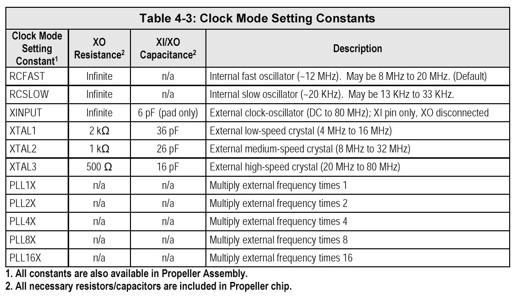
First of all, _CLKMODE is examined. The Clock Mode setting constant is defined in Table 4-3 of the Propeller reference manual on page 180 as follows.
It confirms it in Blinker2.spin used with Exercise 7-8, and for instance, _CLKMODE setting was able to have been added to the CON block by only one line, and to confirm the operation of slowing Propeller to/by executing following Blinker3.spin.
{{ Blinker3.spin }}

CON
	_CLKMODE = RCSLOW 	'Set to internal slow clock
	MAXLEDS = 6 	'Number of LED objects to use

OBJ
	LED[6] : "Output"

PUB Main
{Toggle pins at different rates, simultaneously}
	dira[16..23]~~ 				'Set pins to outputs
	LED[NextObject].Start(16, 3_000_000, 0) 	'Blink LEDs
	LED[NextObject].Start(17, 2_000_000, 0)
	LED[NextObject].Start(18, 600_000, 300)
	LED[NextObject].Start(19, 6_000_000, 40)
	LED[NextObject].Start(20, 350_000, 300)
	LED[NextObject].Start(21, 1_250_000, 250)
	LED[NextObject].Start(22, 750_000, 200) 	'<-Postponed
	LED[NextObject].Start(23, 400_000, 160) 	'<-Postponed
	LED[0].Start(20, 12_000_000, 0) 	'Restart object 0
	repeat 					'Loop endlessly

PUB NextObject : Index
{Scan LED objects and return index of next available LED object. Scanning continues until one is available.}
	repeat
		repeat Index from 0 to MAXLEDS-1
			if not LED[Index].Active
				quit
	while Index == MAXLEDS
If the statement of "_CLKMODE = RCSLOW" of the CON block of this program is replaced with "_CLKMODE = RCFAST", it becomes the speed of default similar to Blinker2.spin.
In addition, when the external clock element with high frequency accuracy (quartz vibrator/ceramic resonator) is connected outside of Propeller, various options of _CLKMODE can be used. The crystal of 5MHz installed in Propeller Demo Board is used here. It was executed at half (12MHz to 5MHz) the speed of operation for default when seeing as Blinker4.spin that changed the description of the CON block of Blinker3.spin as follows.
{{ Blinker4.spin }}

CON
	_CLKMODE = XTAL1 	'Set to ext. low-speed crystal
	_XINFREQ = 5_000_000		' Frequency on XIN pin is 5 MHz
	MAXLEDS = 6 	'Number of LED objects to use

OBJ
	LED[6] : "Output"

PUB Main
{Toggle pins at different rates, simultaneously}
	dira[16..23]~~ 				'Set pins to outputs
	LED[NextObject].Start(16, 3_000_000, 0) 	'Blink LEDs
	LED[NextObject].Start(17, 2_000_000, 0)
	LED[NextObject].Start(18, 600_000, 300)
	LED[NextObject].Start(19, 6_000_000, 40)
	LED[NextObject].Start(20, 350_000, 300)
	LED[NextObject].Start(21, 1_250_000, 250)
	LED[NextObject].Start(22, 750_000, 200) 	'<-Postponed
	LED[NextObject].Start(23, 400_000, 160) 	'<-Postponed
	LED[0].Start(20, 12_000_000, 0) 	'Restart object 0
	repeat 					'Loop endlessly

PUB NextObject : Index
{Scan LED objects and return index of next available LED object. Scanning continues until one is available.}
	repeat
		repeat Index from 0 to MAXLEDS-1
			if not LED[Index].Active
				quit
	while Index == MAXLEDS
It becomes this mode to which the clock of Propeller is specified for an outside low-speed crystal by "_CLKMODE = XTAL1", and the oscillator in Propeller drives an external crystal of 16MHz from 4MHz. Propeller only has to connect the crystal XI of Propeller and between terminals of XO though there is the one to need the ceramic capacitor of about 10pF for an external crystal in addition in single-chip CPU, too.
When the oscillator or the clock signal input of the outside is used, it is necessary to describe _XINFREQ or _CLKFREQ in addition to _CLKMODE. _XINFREQ describes the system clock frequency from which frequency that enters the XI pin from an external crystal and _CLKFREQ are supplied. These two relates to PLL setting described later.
In the example of Blinker4.spin, by "_XINFREQ = 5_000_000" The crystal of 5MHz is connected between XI pin XO pins of Propeller because it is described that the input of the XI pin is 5MHz. As a result, the value of _CLKFREQ is automatically set by Propeller Tool.
When _CLKFREQ is specified 5MHz oppositely, Propeller Tool sets the value of _XINFREQ. However, specification here is desirable _XINFREQ because there is a clock setting with PLL described later. It is a mistake though the frequency named 5MHz of an external crystal has the impression (great and slowness) compared with general building in CPU. If Blinker5.spin that only only part is different is compiled and executed, it understands as follows.
{{ Blinker5.spin }}

CON
	_CLKMODE = XTAL1 + PLL4X	'Set to ext. low-speed crystal, 4x PLL
	_XINFREQ = 5_000_000		' Frequency on XIN pin is 5 MHz
	MAXLEDS = 6 	'Number of LED objects to use

OBJ
	LED[6] : "Output"

PUB Main
{Toggle pins at different rates, simultaneously}
	dira[16..23]~~ 				'Set pins to outputs
	LED[NextObject].Start(16, 3_000_000, 0) 	'Blink LEDs
	LED[NextObject].Start(17, 2_000_000, 0)
	LED[NextObject].Start(18, 600_000, 300)
	LED[NextObject].Start(19, 6_000_000, 40)
	LED[NextObject].Start(20, 350_000, 300)
	LED[NextObject].Start(21, 1_250_000, 250)
	LED[NextObject].Start(22, 750_000, 200) 	'<-Postponed
	LED[NextObject].Start(23, 400_000, 160) 	'<-Postponed
	LED[0].Start(20, 12_000_000, 0) 	'Restart object 0
	repeat 					'Loop endlessly

PUB NextObject : Index
{Scan LED objects and return index of next available LED object. Scanning continues until one is available.}
	repeat
		repeat Index from 0 to MAXLEDS-1
			if not LED[Index].Active
				quit
	while Index == MAXLEDS
As for the difference here, "_CLKMODE = XTAL1" only became "_CLKMODE = XTAL1 + PLL4X". In this, cycle number [**] twice that four frequencies of XIN are multiplied with the PLL(phase-locked loop) in Propeller circuit are done, and the system clock is 5MHz * 4 = It means becoming 20MHz. (12MHz < 20MHz) Actually, operation became early more almost twice as much than default.
Propeller Tool calculates the value of _CLKFREQ by the automatic operation with 20MHz in assuming _XINFREQ to be 5MHz, and specifying PLL4X in addition in this example. It is disregarded even if it dares to be described, "_ CLKFREQ is 5MHz" further here. Therefore, you seem should use _XINFREQ by the clock frequency specification in the CON block including the case with clock [**] twice with PLL when an external crystal is used.
There are five kinds of the following when an external crystal is assumed to be 5MHz to the configuration option of clock generation PLL of Propeller.
When "_CLKMODE = XTAL1 + PLL4X" is assumed to be "_CLKMODE = XTAL1 + PLL16X" here, the system clock is 5MHz * 16 = It becomes 80MHz. In this case, PLL2X to say nothing of PLL16X is also useless though it seems to be able to use an external crystal for 60MHz in the maximum. It is glad that the upper bound of the system clock can achieve even 80MHz by a cheap crystal of 5MHz though it is 80MHz certain. As the built-in microcomputer, clock 80MHz is a considerably high-speed ability. Propeller ..scaring.. [rubeshi].
- PLL1X - 5MHz
- PLL2X - 10MHz
- PLL4X - 20MHz
- PLL8X - 40MHz
- PLL16X - 80MHz
Well, it is an example of correcting a part of the sample program that has been used for here in Exercise 10 even if the definition related to the clock goes out. The Propeller chip is ..clock.. revokable while even executing it. Then, the delay is not a number of clocks, and is improved to the technique for describing it as actual time. The overlapping annotation is omitted, and improved Output.spin is as follows.
{{ Output.spin }}

VAR
	long Stack[9]
	byte Cog

PUB Start(Pin, DelayMS, Count): Success
	Stop
	Success := (Cog := cognew(Toggle(Pin, Delay, Count), @Stack) + 1)

PUB Stop
	if Cog
	cogstop(Cog~ - 1)

PUB Active: YesNo
	YesNo := Cog > 0

PUB Toggle(Pin, DelayMS, Count)
	dira[Pin]~~
	repeat
		!outa[Pin]
		waitcnt(clkfreq / 1000 * DelayMS + cnt) 		'Wait for DelayMS
	while Count := --Count #> -1
	Cog~
Here, the delay parameter named Delay counted as a number of clocks was changed to DelayMS of each millisecond. Symbol CLKFREQ is a returned command. ..included actual system clock.. Hz(Cycle per second) it even to PLL A final delay becomes "Delay of the DelayMS millisecond" because it becomes the unit of the millisecond by having divided this by 1000, and it multiplies by DelayMS.
When the system clock is changed when Propeller is executed, CLKSET command is used. In this case, this Output object is reviving counted the delay and corresponds to each loop no matter how the system clock is changed. The program of Blinker6.spin of one sample that changes the Top side becomes the following corresponding to this Output.spin.
{{ Blinker6.spin }}

CON
	_CLKMODE = XTAL1 + PLL4X	'Set to ext. low-speed crystal, 4x PLL
	_XINFREQ = 5_000_000		' Frequency on XIN pin is 5 MHz
	MAXLEDS = 6 	'Number of LED objects to use

OBJ
	LED[6] : "Output"

PUB Main
	dira[16..23]~~ 				'Set pins to outputs
	LED[NextObject].Start(16, 250, 0) 	'Blink LEDs
	LED[NextObject].Start(17, 500, 0)
	LED[NextObject].Start(18, 50, 300)
	LED[NextObject].Start(19, 500, 40)
	LED[NextObject].Start(20, 29, 300)
	LED[NextObject].Start(21, 104, 250)
	LED[NextObject].Start(22, 63, 200) 	'<-Postponed
	LED[NextObject].Start(23, 33, 160) 	'<-Postponed
	LED[0].Start(20, 1000, 0) 	'Restart object 0
	repeat 					'Loop endlessly

PUB NextObject : Index
	repeat
		repeat Index from 0 to MAXLEDS-1
			if not LED[Index].Active
				quit
	while Index == MAXLEDS
The error margin of the delay accumulates only the instruction cycle of Propeller in actual operation because it is software DeLay in this example who simply uses WAITCNT command. The method of avoiding this and making to an accurate timer is on page 322 of the Propeller manual, and is said that it should refer to the explanation of WAITCNT. When it saw there, they were two Synchronized Delays.. items, and it considerably explained ..becoming it.. amount Fixed Delays. When an accurate timer was achieved, this decided to be confirmed again sooner or later.
In Exercise 11 of the Propeller manual, it changes radically and Library Objects is described. In Propeller Tool, there are a lot of objects that the engineer of the Parallax Co. developed, and this can be used as a software parts. The example of these libraries includes the following.
Eight Cogs has the video generator respectively, and, because, in being able to use something though it was also in the article on the transistor technology---It expects it.
- Serial communications
- Floating point number value operation
- Mutual conversion of numerical value and character string
- TV display signal generation
- Keyboard of PC standard
- Mouse of PC standard
- Display of PC standard
It was possible to call easily only by browsing the Object library of Propeller Tool, and following Display.spin was called for the time being.
{{ Display.spin }}

CON
	_clkmode = xtal1 + pll16x
	_xinfreq = 5_000_000

OBJ
	Num : "Numbers"
	TV : "TV_Terminal"

PUB Main | Temp
	Num.Init 		'Initialize Numbers
	TV.Start(12) 		'Start TV Terminal

	Temp := 900 * 45 + 401 		'Evaluate expression
	TV.Str(string("900 * 45 + 401 = ")) 		'then display it and
	TV.Str(Num.ToStr(Temp, Num#DDEC)) 		'its result in decimal
	TV.Out(13)
	TV.Str(string("In hexadecimal it's = ")) 		'and in hexadecimal
	TV.Str(Num.ToStr(Temp, Num#IHEX))
	TV.Out(13)
	TV.Out(13)

	TV.Str(string("Counting by fives:")) 		'Now count by fives
	TV.Out(13)
	repeat Temp from 5 to 30 step 5
		TV.Str(Num.ToStr(Temp, Num#DEC))
		if Temp < 30
			TV.Out(",")
Then, information was neatly displayed on the screen of the video monitor (television) that tied from Propeller Demo Board with the RCA cable. This is easy [daa;]. (^_^)
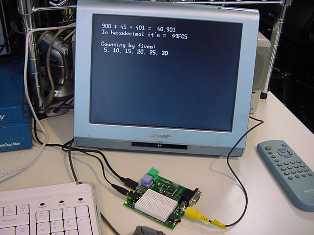
It is in the OBJ block in this program. Two libraries of Numbers and TV_Terminal are used. Numbers is a library where the numerical data is converted into the character string. TV_Terminal is a library where it is displayed in the television (video monitor). It is following information that was displayed in the monitor.
900 * 45 + 401 = 40,901
In hexadecimal it's = $9FC5
Counting by fives:
 5, 10, 15, 20, 25, 30
It is this the analogue signal going out of the RCA video connector of Propeller Demo Board, and being usually displayed in the television quite serious because. Cog that takes charge of this hour by hour generates worth of per second of 60 frames information to the thing that the display stops as it is. It might be effective also for the start of this video display task and the debugging of the system that achieves necessary operation with other Cog to one of Cog of Propeller.
Sunday 9th, March 2008
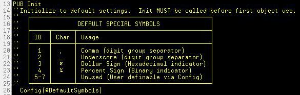
"PUB Main | Temp" that appears in the line of the definition of Main in the code of Display.spin assuming that it is novel is important. The variable named Temp with the length length is defined as a local variable by having declared "| Temp" by using the symbol of "|" quite different from ":" that indicates the return value.In the definition in the OBJ block of Display.spin as "Num :"Numbers"" and "TV :"TV_Terminal"", two programs named Numbers.spin and TV_Terminal.spin in the library are called by the automatic operation. Because Num is Numbers.spin, the Init method in this is called in the first line "Num.Init" of the PUB Main block. When pertinent part (init) in Numbers.spin is seen with Propeller Tool, it is as follows. It is necessary to call this first before all Object of Numbers.spin is called because it is a definition of the default symbol for an internal register setting.
Because TV is TV_Terminal.spin, the second line "TV.Start(12)" of the PUB Main block of Display.spin calls the Start method in this by argument 12. When pertinent part (start) in TV_Terminal.spin is seen, it is as follows. This argument (Symbol named basepin internally) composes the D/A converter that generates the baseband video signal of 1V-75 ohm of three I/O pins (It is P12, P13, and P14 here) from the pin by the resistance of external 1.1K ohm, 560 ohm, and 270 ohm in specification (boundary of each every of the four pins) which I/O pin of the Propeller chip to make a base. Additionally, to generate the video signal, two Cogs or more is started. The method named Init or Start generally will be called first the use of the object though the document of use etc. is included in the source of the object like these examples.
PUB start(basepin)

'' Start terminal
''  basepin = first of three pins on a 4-pin boundary (0, 4, 8...) to have
''  1.1k, 560, and 270 ohm resistors connected and summed to form the 1V,
''  75 ohm DAC for baseband video

'init bitmap and tile screen
bitmap_base := (@bitmap + $3F) & $7FC0
repeat x from 0 to x_tiles - 1
	repeat y from 0 to y_tiles - 1
		screen[y * x_tiles + x] := bitmap_base >> 6 + y + x * y_tiles

'start tv
tvparams_pins := (basepin & $38) << 1 | (basepin & 4 == 4) & %0101
longmove(@tv_status, @tvparams, paramcount)
tv_screen := @screen
tv_colors := @color_schemes
tv.start(@tv_status)

'start graphics
gr.start
gr.setup(x_tiles, y_tiles, 0, y_screen, bitmap_base)
gr.textmode(x_scale, y_scale, x_spacing, 0)
gr.width(width)
out(0)
The following four lines correspond from the third line following this of Main of Display.spin to the part displayed in the first line of the video outlet as "900 * 45 + 401 = 40,901". The statement of the first "Temp := 900 * 45 + 401" is 900 in local variable Temp * 45 + 401 was substituted.
Temp := 900 * 45 + 401 		'Evaluate expression
TV.Str(string("900 * 45 + 401 = ")) 		'then display it and
TV.Str(Num.ToStr(Temp, Num#DDEC)) 		'its result in decimal
TV.Out(13)
When pertinent part (str) in TV_Terminal.spin is seen to examine the following "TV.Str(string("900 * 45 + 401 ="))", it is as follows. The character string is defined by the directive (instruction)STRING that appears here. In Propeller, the string is [ta-mineito]ed by 0(NULL) as well as C and Java. This is called z-string. The byte with the initial address and 0 values of the string will be assumed to be an end of the string in the majority of character-string handling in Propeller. As for this TV.Str, the REPEAT sentence has ended processing by the trailing zero.
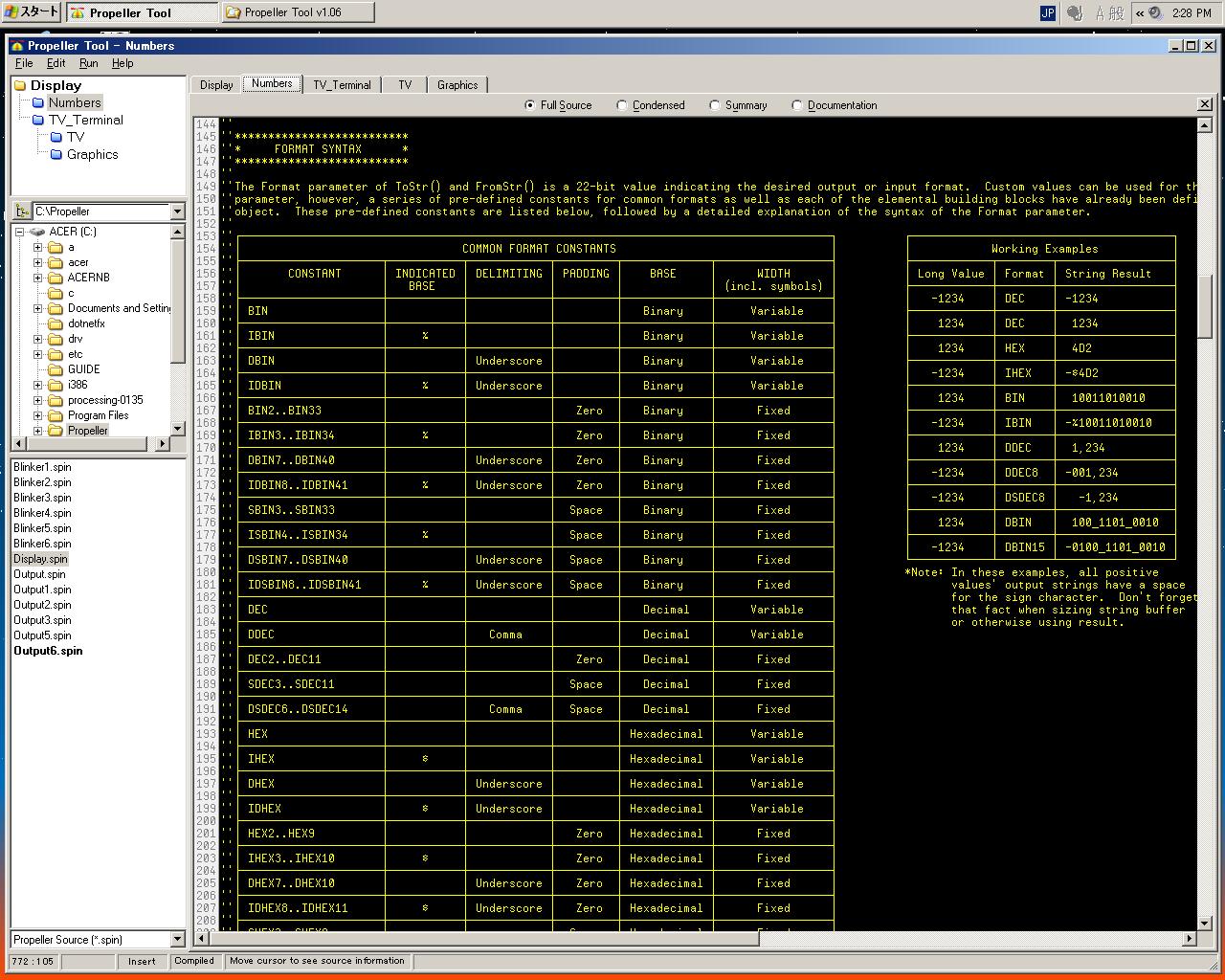
PUB str(string_ptr)
'' Print a zero-terminated string
	repeat strsize(string_ptr)
		out(byte[string_ptr++])
This following "TV.Str(Num.ToStr(Temp, Num#DDEC))" converts the value of local variable Temp into the string with delimited decimal format. The "#" symbol of "Num#DDEC" that appears newly is a meaning of "Object reference constant". Here, it becomes a meaning of using synoptical defined in the Number object as follows as format constant "DDEC". After numerical value "40901" is converted into "40,901" of Thousand delimiter (The comma is placed every three digits) form, this is converted into the character string of the NULL end. The return value of this TV.Str is an initial address of the string.
The last "TV.Out(13)" of this a series of display program outputs one byte of "13" to the display. The following text display position is moved to "Head of the following line to which it changes line" for TV_Terminal though 13 of the ASCII codes is "Carriage return (CR)", and it doesn't see it in the display. The display after this is ..same as above.. already clear.
Refer to the object of tv.spin and graphics.spin for the TV_Terminal object in that in addition as follows. Not only the spin language but also both are long large programs, and masses of the Propeller assembler. It is assumed that the customizing remodeling of this detail is done sooner or later. It seems to be able to use this only as a software parts of the Black Box for the time being.
Propeller Tool displays these related objects retrieving, and collectively. Understanding that there is Linrary folder that the Work folder and the system that I original produce offer in the program might be important. It is this, and Exercise 11 is [oshimai].OBJ tv : "tv" gr : "graphics"Well, the last it is Exercise, and the topic is [dearu] of the Propeller tutorial in Exercise 12 and this more and more as for the treatment of various numeric representations of Propeller. The basis : as an integer with the sign. The numerical value of 2,147,483,647 can be treated from -2,147,483,648 as a constant, and it use it as a run time numerical value expression. In addition..compiler..integer..fixed-point number representation..real..numerical value..interchangeable..form..sign bit..index..mantissa..figure below..floating point..correspond. The library group of Propeller also is supporting all these numeric representations.
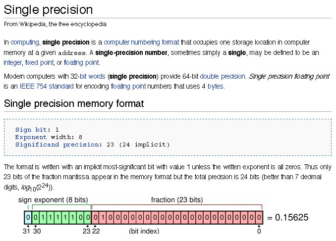
First of all, it is [dearu] as for Pseudo-Real Numbers, that is, the numeric representation of the integer and the fixed zero point. For instance, the value 23.56 is obtained as a result of "A = 7.6 * 38.75 / 12.5" when specifying, "Two digits after the decimal point" for a numeric operation of "A = B * C / D". This will have been treated as follows at run time as an integer in which all of the 100 numerical values are multiplied.
A = (B* 100) * (C * 100) / (D * 100)
A = (7.6 * 100) * (38.75 * 100) / (12.5 * 100)
A = 760 * 3875 / 1250
A = 2356
It operates like this by 100 numerical values multiplied respectively, and the result is obtained as 2356 / 100 = 23.56 at the end. Any stage of the process : when operating it like this ..it is necessary to note it... From -2,147,483,648 to beyond the pale should not, and 2,147,483,647 thing it with limitation
Next, it is [dearu] as for Floating-Point Numbers, that is, the floating point. The processing settled with above-mentioned Pseudo-Real Numbers is written that it is necessary to use that as much as possible according to the Propeller manual. The floating point library is used please if there is room at the execution speed because it takes a considerable time when executing it though is the degree of freedom of the expression. ---The tone of argument. When the spin interpreter executes it, an integer alone, and, maybe, it seems not to be used directly to treat. Because it was a way, it passed though it did not use very much though there was a sample named RealNumbers.spin at the Chapter 3 end after this. When you see FloatMath.spin (the following lists) referred to in that It is because it is a numeric operation library that is often by the multiplication by the integer has been separately written up to now by building in CPU and the combination of division. The end was to have become it so after all even though an excellent Propeller chip.
PUB FFloat(integer) : single | s, x, m
	if m := ||integer             'absolutize mantissa, if 0, result 0
		s := integer >> 31          'get sign
		x := >|m - 1                'get exponent
		m <<= 31 - x                'msb-justify mantissa
		m >>= 2                     'bit29-justify mantissa
	    return Pack(@s)             'pack result

PUB FRound(single) : integer
	return FInteger(single, 1)    'use 1/2 to round

PUB FTrunc(single) : integer
	return FInteger(single, 0)    'use 0 to round

PUB FNeg(singleA) : single
	return singleA ^ $8000_0000   'toggle sign bit

PUB FAbs(singleA) : single
	return singleA & $7FFF_FFFF   'clear sign bit

PUB FSqr(singleA) : single | s, x, m, root
	if singleA > 0                'if a =< 0, result 0
		Unpack(@s, singleA)         'unpack input
		m >>= !x & 1                'if exponent even, shift mantissa down
		x ~>= 1                     'get root exponent
	root := $4000_0000          'compute square root of mantissa
	repeat 31
		result |= root
		if result ** result > m
			result ^= root
		root >>= 1
	m := result >> 1
	return Pack(@s)             'pack result

PUB FAdd(singleA, singleB) : single | sa, xa, ma, sb, xb, mb
	Unpack(@sa, singleA)          'unpack inputs
	Unpack(@sb, singleB)
	if sa                         'handle mantissa negation
		-ma
	if sb
		-mb
	result := ||(xa - xb) <# 31   'get exponent difference
	if xa > xb                    'shift lower-exponent mantissa down
		mb ~>= result
	else
		ma ~>= result
		xa := xb
	ma += mb                      'add mantissas
	sa := ma < 0                  'get sign
	||ma                          'absolutize result
  return Pack(@sa)              'pack result

PUB FSub(singleA, singleB) : single
	return FAdd(singleA, FNeg(singleB))

PUB FMul(singleA, singleB) : single | sa, xa, ma, sb, xb, mb
	Unpack(@sa, singleA)          'unpack inputs
	Unpack(@sb, singleB)
	sa ^= sb                      'xor signs
	xa += xb                      'add exponents
	ma := (ma ** mb) << 3         'multiply mantissas and justify
	return Pack(@sa)              'pack result

PUB FDiv(singleA, singleB) : single | sa, xa, ma, sb, xb, mb
	Unpack(@sa, singleA)          'unpack inputs
	Unpack(@sb, singleB)
	sa ^= sb                      'xor signs
	xa -= xb                      'subtract exponents
	repeat 30                     'divide mantissas
		result <<= 1
		if ma => mb
			ma -= mb
			result++
		ma <<= 1
	ma := result
	return Pack(@sa)              'pack result

PRI FInteger(a, r) : integer | s, x, m
	Unpack(@s, a)                 'unpack input
	if x => -1 and x =< 30        'if exponent not -1..30, result 0
		m <<= 2                     'msb-justify mantissa
		m >>= 30 - x                'shift down to 1/2-lsb
		m += r                      'round (1) or truncate (0)
		m >>= 1                     'shift down to lsb
		if s                        'handle negation
			-m
		return m                    'return integer

PRI Unpack(pointer, single) | s, x, m
	s := single >> 31             'unpack sign
	x := single << 1 >> 24        'unpack exponent
	m := single & $007F_FFFF      'unpack mantissa
	if x                          'if exponent > 0,
		m := m << 6 | $2000_0000    '..bit29-justify mantissa with leading 1
	else
		result := >|m - 23          'else, determine first 1 in mantissa
		x := result                 '..adjust exponent
		m <<= 7 - result            '..bit29-justify mantissa
	x -= 127                      'unbias exponent
	longmove(pointer, @s, 3)      'write (s,x,m) structure from locals

PRI Pack(pointer) : single | s, x, m
	longmove(@s, pointer, 3)      'get (s,x,m) structure into locals
	if m                          'if mantissa 0, result 0
		result := 33 - >|m          'determine magnitude of mantissa
		m <<= result                'msb-justify mantissa without leading 1
		x += 3 - result             'adjust exponent
		m += $00000100              'round up mantissa by 1/2 lsb
		if not m & $FFFFFF00        'if rounding overflow,
			x++                       '..increment exponent
		x := x + 127 #> -23 <# 255  'bias and limit exponent
		if x < 1                    'if exponent < 1,
			m := $8000_0000 +  m >> 1 '..replace leading 1
			m >>= -x                  '..shift mantissa down by exponent
			x~                        '..exponent is now 0
	return s << 31 | x << 23 | m >> 9 'pack result
Chapter 3 ends by this, too. Because the remainder of the Propeller manual is a reference of the spin language and the Propeller assembler, the study of the Propeller manual can be called an end by this. How it cost it here was written as follows. Indeed, [a;] ..whether it is independence... (^_^;)
Where to go from here...
You should now have the knowledge you need to explore the Propeller
chip on your own and develop your first applications. Use the rest of
this manual as a reference to the Spin and Propeller Assembly languages,
explore every existing library object that interests you and join the
Propeller Forum to keep learning and sharing with other active Propeller
chip users.

Propeller Diary (2)