Propeller Diary (2)
Yoichi Nagashima

Propeller Diary (1)
Monday 10th, March 2008
The following two decided to be assumed to be a text from PDF on the site of the Parallax Co. as the following practice in the place where the tutorial of the Propeller manual had been finished - This and This . However, this text (It seemed to be called Lab) was set and because it was not interesting to run after the state as it is, either the target of my own way was set.To begin with, the tutorial of the Propeller manual already was assumed to be ..trial of "Where does the performance go out by single Cog?".. plan here though tried to the method of starting two or more Cogs. It makes to 80MHz of the maximum performance by 16 time PLL mode, and, then, 5MHz crystal of Propeller Demo Board wants to test to the clock whether it is possible to work by using the main memory (It is compulsorily time-shared and it is made to wait) with single Cog for where.
And, only this task exceptionally processed in parallel because it tried the sample of the video outlet secondarily with great pains, and inside information was assumed to display the video separately. It is perhaps because of the experience as much as possible because I want to use the video outlet as a back monitor or a visual installation of the standalone if it will be possible to do in the future though this becomes an experiment that deviates from the text.
The first "Read of the input", "Judgment", and "Control of the output" that the majority of CPU does in "Fundamentals: Propeller I/O and Timing Basics" are arranged. About the input and the output, it is sensitive to timing in most cases, and becomes operation "Watch of the input" and "Update of the output". In this Fundamentals, "LED lighting" circuit is set to the I/O pin of the Propeller chip as "Pushbutton" circuit and a sample of the update of the output and it uses it as a sample of the watch of the input. Even if it becomes other circuits as an application, this is basically equal as the principle of operation of the software of Propeller. It is said that the following applications can be done by mastering this Lab text.
- Turn an LED on - assigning I/O pin direction and output state
- Turn groups of LEDs on - group I/O assignments
- Signal a pushbutton state with an LED - monitoring an input, and setting an output accordingly
- Signal a group of pushbutton states with LEDs - parallel I/O, monitoring a group of inputs and writing to a group of outputs
- Synchronized LED on/off signals - event timing based on a register that counts clock ticks
- Configure the Propeller chipˇÇs system clock - choosing a clock source and configuring the Propeller chipˇÇs Phase-Locked Loop (PLL) frequency multiplier
- Display on/off patterns - Introduction to more Spin operators commonly used on I/O registers
- Display binary counts - introductions to several types of operators and conditional looping code block execution
- Shift a light display - conditional code block execution and shift operations
- Shift a light display with pushbutton-controlled refresh rate - global and local variables and more conditional code block execution
- Timekeeping application with binary LED display of seconds - Introduction to synchronized event timing that can function independently of other tasks in a given cog.
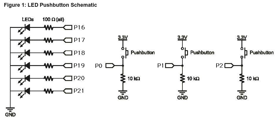
In the Lab text, the following schematic diagrams are shown as "Parts List and Schematic".

However, it is as follows in Propeller Demo Board in hand.
Then, they decided to be made to part from PDF, and to correspond to Propeller Demo Board, and to change the allocation of the port as follows. How different from original lighting processing to see it only has to resist about LED and ..a certain possibility.. to note it via.
- Because P0-P7 has freely become empty, it is possible to connect it with a universal substrate.
- P8-P11 is an output of the mike input for A/D and the headphone output amplifier.
- P12-P15 is D/A for the RCA video outlet.
- As for P16-P23, LED is connected, and each other is connected with the resistance for the VGA output.
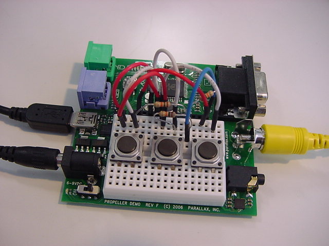
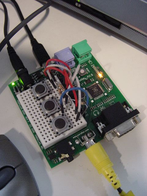
It actually wired on Propeller Demo Board for three switch and resistance. The circuit more than this doesn't seem to enter if the breadboard construction is not extended to the outside.

In the Lab text, the term that has been studied with the Propeller manual as follows is arranged as "Propeller Nomenclature" (Propeller nomenclature) following this. It is assumed that spin is treated in the Lab text though there are two languages of spin and the assembler in the programming of Propeller. Moreover, it makes it only to the sample that treats Top Object alone in this Lab.
- Cog - a processor inside the Propeller chip. The Propeller chip has eight cogs, making it possible to perform lots of tasks in parallel. The Propeller is like a super-microcontroller with eight high speed 32-bit microcontrollers inside. Each internal microcontroller (cog) has access to the Propeller chipˇÇs I/O pins and 32 KB of global RAM. Each cog also has its own 2 KB of ram that can either run a Spin code interpreter or an assembly language program.
- Spin and assembly languages - The Spin language is the high-level programming language created by Parallax for the Propeller chip. Cogs executing Spin code do so by loading a Spin interpreter from the Propeller chipˇÇs ROM. This interpreter fetches and executes Spin command codes that get stored in the Propeller chipˇÇs Global Ram.
- Method - block of executable Spin commands that has a name, access rule, and can optionally receive and return parameter values and create local (temporary) variables.
- Global and local variables - Global variables are available to all the methods in a given object, and they reserve variable space as long as an application is running. Local variables are defined in a method, can only be used within that method, and only exist while that method executes commands. When itˇÇs done, the memory these local variables used becomes available to for other methods and their local variables. Local and global variables are defined with different syntax.
- Object - an application building block comprised of all the code in a given .spin file. Some Propeller applications use just one object but most use several. Objects have a variety of uses, depending partially on how they are written and partially on how they get configured and used by other objects. Some objects serve as top level objects, which provide the starting point where the first command in a given application gets executed. Other objects are written to provide a library of useful methods for top level or other objects to use.
Well, it becomes a source different from the sample of PDF because the number of the port has been changed, and it experiments on the video outlet at the same time here though it is a sample program more and more. For instance, the sample source recorded first is the following.
'' File: LedOnP4.spin

	PUB LedOn 		' Method declaration
		dira[4] := 1 		' Set P4 to output
		outa[4] := 1 		' Set P4 high
	repeat 			' Endless loop prevents program from ending
However, this was actually changed to the following programs.
{{ exp001.spin }}

CON
	_clkmode = xtal1 + pll16x
	_xinfreq = 5_000_000

OBJ
	Num : "Numbers"
	TV : "TV_Terminal"

PUB Main
	Monitor
	LedOn

PUB Monitor | Temp
	Num.Init                                              'Initialize Numbers
	TV.Start(12)                                          'Start TV Terminal
	Temp := 900 * 45 + 401                                'Evaluate expression
	TV.Str(string("900 * 45 + 401 = "))                   'then display it and
	TV.Str(Num.ToStr(Temp, Num#DDEC))                     'its result in decimal
	TV.Out(13)
	TV.Str(string("Counting by fives:"))                  'Now count by fives
	repeat Temp from 5 to 30 step 5
		TV.Str(Num.ToStr(Temp, Num#DEC))
		if Temp < 30
			TV.Out(",")

PUB LedOn
	dira[16] := 1                                         ' Set P4 to output
	outa[16] := 1                                         ' Set P4 high
	repeat                                                ' Endless loop prevents program from ending
The message of two lines was displayed in the video monitor when this was compiled, and executed, and, in addition, LED of P16 lit. It has been understood for the Monitor method of the video outlet to call an infinite loop of the display processing in Cog internally though it is sure to specify and to end and to return about former method. Here, nothing was displayed in the video when only the part of Main was changed by way of experiment and it reversed it as follows though LED of P16 lit.
PUB Main
	LedOn
	Monitor
The purpose of this is for LedOn of the first line of the Main method to be called, and not to come back from the last infinity REPEAT. might
It returned to exp001.spin again, and, this time, LED of P16 did not light when the last REPEAT of the LedOn method was erased. This is because Propeller moves to the low power mode after lighting of LED at the moment not visible because the method was executed even the last statement and became "End", and the I/O pin initial (standby) returned to "Input". Cog manages the output register as an output status in Propeller rather than CPU's writing it in the I/O port. Even if it parts from the control of Cog, the state of the I/O pin is noted, and the latch is not done, and it is necessary to seem to note it because the idea is different from other CPU such as AKI-H8.
How does Propeller operate in the Lab text following this? I passed because I understood this from the tutorial of the Propeller manual already though the explanation continued. However, it came to want to experiment on the confirmation for a moment in the explanation "When it tried to use the I/O pin as which two or more Cog was the same, become Wired-OR". Then, Output.spin that had been made before was called, and new exp002.spin was made as follows.
{{ exp002.spin }}

CON
	_clkmode = xtal1 + pll16x
	_xinfreq = 5_000_000
	MAXLEDS = 6 'Number of LED objects to use

OBJ
	Num : "Numbers"
	TV : "TV_Terminal"
	LED[6] : "Output"

PUB Main
	Monitor
	dira[16..23]~~ 			'Set pins to outputs
	LED[NextObject].Start(16, 50, 0)
	LED[NextObject].Start(16, 1000, 0)

PUB Monitor | Temp
	Num.Init                                              'Initialize Numbers
	TV.Start(12)                                          'Start TV Terminal
	Temp := 900 * 45 + 401                                'Evaluate expression
	TV.Str(string("900 * 45 + 401 = "))                   'then display it and
	TV.Str(Num.ToStr(Temp, Num#DDEC))                     'its result in decimal
	TV.Out(13)
	TV.Str(string("Counting by fives:"))                  'Now count by fives
	repeat Temp from 5 to 30 step 5
		TV.Str(Num.ToStr(Temp, Num#DEC))
		if Temp < 30
			TV.Out(",")

PUB NextObject : Index
	repeat
		repeat Index from 0 to MAXLEDS-1
			if not LED[Index].Active
				quit
	while Index == MAXLEDS
"Same P16" of the point of this experiment is pin specification though it dares to call the LED lighting processing with different one after another Cog. LED of P16 alternately repeats the following when compiling and executing it.
In this, the output to P16 is exactly a thing that Wired-OR is done. In the example of this exp002.spin, this statement of four lines has ended as Main method. However, because Cog called in each runs in an infinite loop, the character of the video monitor and the blinking operation of LED are consecutive. It is feelings not settled for a moment either though is so if it is said that you may not worry about "How many Cog are running now?" as the program. It will also experiment also on this later.
- It lights continuously for one second.
- It blinks in detail for one second.
It was when the following two statements were the same after this in the Lab text.
	dira[16] := 1
	outa[16] := 1
dira[16] := outa[16] := 1There was the following examples following this it was possible to do bringing the definition of the I/O pin together.
dira[16..21] := %111111 outa[16..21] := %101010"%" is synoptical used by a lot of phases as a description method in a binary binary of this. This is harvested. Pin16 is ON(1) and Pin17 is OFF(0) if it describes it as follows. ---..becoming..
outa[16..21] := %101010However, Pin21 is ON(1) and Pin20 is OFF(0) if this is reversed and it describes it as follows. ---It becomes it.
outa[21..16] := %101010It corresponds in the ascending order and the descending order in a word, and the bit map of substitution is "Appearing order. "
The Lab text continuously became "Reading an Input, Controlling an Output". It is the first port input more and more. It is ina register that shows the input, and says that this returns the value of the outa register when the port is specified for the output by dira. It becomes Low(0) if it ..High(1).. doesn't exceed it if the voltage of the input pin has exceeded 1.65V of the [sureshorudo] voltage because Propeller operates in 3.3V power supply. When the INA command is executed, the content of ina register is updated. Then, when you execute following exp003.spin making it LED of Pin18, Pin19, and Pin20 independently did the ON/OFF lighting operation respectively corresponding to the button switch splendidly put on the breadboard construction on Propeller Demo Board.
{{ exp003.spin }}

CON
	_clkmode = xtal1 + pll16x
	_xinfreq = 5_000_000
	MAXLEDS = 6 'Number of LED objects to use

OBJ
	Num : "Numbers"
	TV : "TV_Terminal"
	LED[6] : "Output"

PUB Main
	Monitor
	dira[16..23]~~ 'Set pins to outputs
	LED[NextObject].Start(16, 50, 0)
	LED[NextObject].Start(16, 1000, 0)

	dira[0..2] ~                                          ' Set to Input (redundant)
	repeat
		outa[18] := ina[0]
		outa[19] := ina[1]
		outa[20] := ina[2]

PUB Monitor | Temp
	Num.Init                                              'Initialize Numbers
	TV.Start(12)                                          'Start TV Terminal
	Temp := 900 * 45 + 401                                'Evaluate expression
	TV.Str(string("900 * 45 + 401 = "))                   'then display it and
	TV.Str(Num.ToStr(Temp, Num#DDEC))                     'its result in decimal
	TV.Out(13)
	TV.Str(string("Counting by fives:"))                  'Now count by fives
	repeat Temp from 5 to 30 step 5
		TV.Str(Num.ToStr(Temp, Num#DEC))
		if Temp < 30
			TV.Out(",")

PUB NextObject : Index
	repeat
		repeat Index from 0 to MAXLEDS-1
			if not LED[Index].Active
				quit
	while Index == MAXLEDS
The statement in this switch input and the LED output is said that it can describe it like "outa 18..20 := ..ina 0..2.. " according to the Lab text. Moreover, "Ff0000" was shown importantly with the following figures. It is necessary already to note this in the future though it has confirmed with the Propeller manual.

Because this was already-known, it passed though there was a description clock [**] twice etc. with story and PLL of accuracy of the system clock and the quartz vibrator after this. For instance, if it dares to be re-[**], the following descriptions- of the register operation.
PUB BlinkLeds
	dira[16..23] := %111111
	repeat
		outa[16..23] := %111111
		waitcnt(clkfreq/2 + cnt)
		outa[16..23] := %000000
		waitcnt(clkfreq/2 + cnt)
If you use post set operator "~~" and post clear operator "~" for here
PUB BlinkLeds
	dira[16..23]~~
	repeat
		outa[16..23]~~
		waitcnt(clkfreq/2 + cnt)
		outa[16..23]~
		waitcnt(clkfreq/2 + cnt)
It is the same. If this uses reversing operator "!" in each bit further
PUB BlinkLeds
	dira[16..23]~~
	outa[16..23]~~
	repeat
		!outa[16..23]
		waitcnt(clkfreq/2 + cnt)
It becomes the same solving. In addition, the explanation of the binary number and the decimal number etc. continued. The arrangement of LED is chosen after this as the binary number binary. It decided to stop on the way for a moment though the example of the variable increment that "outa[16..23]++" was the same as "outa 16..23 := outa 16..23 + 1" etc. continued with the length. In the following programs exp004.spin, it made it to the system that did local variable dummy in the increment again as Main by the method of the video outlet whenever the event "The switch was pushed" or "The switch was separated" occurred here, and video output the numerical value.
{{ exp004.spin }}

CON
	_clkmode = xtal1 + pll16x
	_xinfreq = 5_000_000
	MAXLEDS = 6 'Number of LED objects to use

OBJ
	Num : "Numbers"
	TV : "TV_Terminal"
	LED[6] : "Output"

PUB Main | Temp, dummy
	Num.Init                      'Initialize Numbers
	TV.Start(12)                  'Start TV Terminal
	Temp := 1000
	TV.Str(string("start "))
	TV.Str(Num.ToStr(Temp, Num#DEC))                     'its result in decimal
	TV.Out(",")

	dira[16..23]~~ 'Set pins to outputs
	LED[NextObject].Start(16, 50, 0)
	LED[NextObject].Start(16, 1000, 0)

	dira[0..2]~                                         ' Set to Input (redundant)
	dummy := ina[0] + ina[1] + ina[2]
	repeat
		outa[18] := ina[0]
		outa[19] := ina[1]
		outa[20] := ina[2]
		if dummy <> ina[0] + ina[1] + ina[2]
			dummy := ina[0] + ina[1] + ina[2]
			Temp++
			TV.Str(Num.ToStr(Temp, Num#DEC))
			TV.Out(",")

PUB NextObject : Index
	repeat
		repeat Index from 0 to MAXLEDS-1
			if not LED[Index].Active
				quit
	while Index == MAXLEDS
ˇˇ
The LED blinking output of P16 is done as another task, and, in addition, the LED lighting corresponding to the switch input is done simultaneously with the video outlet. Any multitask system to here cannot be achieved even with AKI-H8 easily easily. At last, because this moved without trouble, Propeller has become familiar.
Tuesday 11th, March 2008
It is continuously a topic of Conditional Repeat Commands in the Lab text. In the spin language of Propeller, there are a lot of reserved words of the relation of the loop control as follows.Syntax options for repeat make it possible to specify the number of times a block of commands is repeated. They can also be repeated until or while one or more conditions exist, or even to sweep a variable value from a start value to a finish value with an optional step delta.It decided to pass though it was when it explained as many as 11 kinds of "Loops counted up to 20" by the combination of the Puri operator and the post operator. In addition, it additionally explained three kinds of "Loops counted up to 20" by using from and to, and, because, it passed. It understands if experimenting for a moment when the software that moves to such actual [noha] is developed. Because it was a thing that this is in the reference of the Propeller manual, too, it passed in the Lab text though the following continued further.
Because it was a thing that this is in the reference of the Propeller manual, too, it passed. In addition, there was continuously the following explanations.
- Vocabulary of operator of Propeller
- shift operators
- ifandelse
- Variable of VAR block: Byte, word, and long
- Limit Minimum "#>" Operator
- Limit Maximum "<#" Operator
- Relative operator and condition
Because this is tried by chance by the experiment program, and two or more local variables had been discovered the array by the comma, this is passed.
- Global variable (Share by the method of the definition and all objects in VAR block).
- Local variable (Arrange it to the method name by pipe sign "|").
Only the topic the last Timekeeping Applications was paid to attention for a moment because it was important. Because it is a topic of no easiness where the system has the accuracy of the quartz accuracy with the crystal oscillator. Two sample programs of the following are presented here. It is "Clock for one second" to display constant named seconds in port 4-9 in binary by outa 9..4 so to speak"Example of management at bad time" first of all.
CON
	_xinfreq = 5_000_000
	_clkmode = xtal1 + pll1x

VAR
	long seconds

PUB BadTimeCount
	dira[9..4]~~
	repeat
		waitcnt(clkfreq + cnt)
		seconds ++
		outa[9..4] := seconds
And, "Example of the management at good time. "
CON
	_xinfreq = 5_000_000
	_clkmode = xtal1 + pll1x

VAR
	long seconds, dT, T

PUB GoodTimeCount
	dira[9..4]~~
	dT := clkfreq
	T := cnt
	repeat
		T += dT
		waitcnt(T)
		seconds ++
		outa[9..4] := seconds
In "Example of the management at bad time", cnt is not counted to execute the addition processing while this.. operating it while ordering waitcnt in the REPEAT loop, and the delay is added to the measurement at the entire time. When this is piled, a fatal error margin is caused as a clock.
The error margin doesn't arise because it calculates the processing time of waitcnt in "Example of the management at good time" by dT and T defined as a variable. The example of "Clock" program that uses this is the following. This idea will become standard in the scene that needs an accurate interval time like the baud rate etc. of the sampling period of audio or serial communications.
CON
	_xinfreq = 5_000_000
	_clkmode = xtal1 + pll1x

VAR
	long seconds, minutes, hours, days, dT, T

PUB GoodClock
	dira[9..4]~~
	dT := clkfreq
	T := cnt
	repeat
		T += dT
		waitcnt(T)
		seconds++

		if seconds // 60 == 0
			minutes++
			if minutes == 60
				minutes := 0
		if seconds // 3600 == 0
			hours++
			if hours == 24
				hours := 0
		if seconds // 86400 == 0
			days++
			outa[9..4] := seconds
In this, completion it- this . Next, the following decided to be tried. - this . The title is clear Methods and Cogs Part and object oriented programming of basis of Propeller It is "Wall" that might not be able to be understood from the part of "Liver", and still present it completely.
In Introduction, the method in spin is first arranged as follows.
- The object is composed of the block that is called a method.
- The method name is used for the programmed control, and can exchange the parameter by the method fellow in spin.
- It is called method call that a certain method uses other methods.
- The method of doing call returns to the call origin with the return value when it ends.
- It can be described that the method receives the parameter (argument) from the call origin.
- The argument is often used initialization, the operation definition, and to hand over the operation value etc.
The method starts distinct Cog here in parallel respectively as for Propeller though it becomes original. The spin language has method and it has instruction that stops the starting instruction, the instruction that specifies Cog, and Cog in Cog. The global variable array : so that the spin method is started by Cog. It is necessary to be defined to allocate the return address of the method in the memory. This memory is called stack space.
As for the call of the method, the return, and the delivery of the argument, it is similar to C and Java. For instance, all the arguments to method Blink that calls from method BlinkTest become substitutions for the item of the list of the parameter of the local variable in the following examples. This method can ..others.. be called by recycling by using a different parameter by doing like this.
PUB BlinkTest
	Blink(4, clkfreq/3, 9)

PUB Blink(pin, rate, reps)
	dira[pin]~~
	outa[pin]~
	repeat reps * 2
		waitcnt(rate/2 + cnt)
		!outa[pin]
On the other hand, it secures (about 10Longs a method), Cog corresponding to each COGNEW command starts then, and the parallel processing can achieve stack as follows. Because Cog(0) is automatically used for the method at the Top level by which each Cogs is started, three started Cogs newly becomes Cog(3) from Cog(1). The argument parameter is different respectively though method Blink is called together, and different processing can be achieved at the time of blinking.
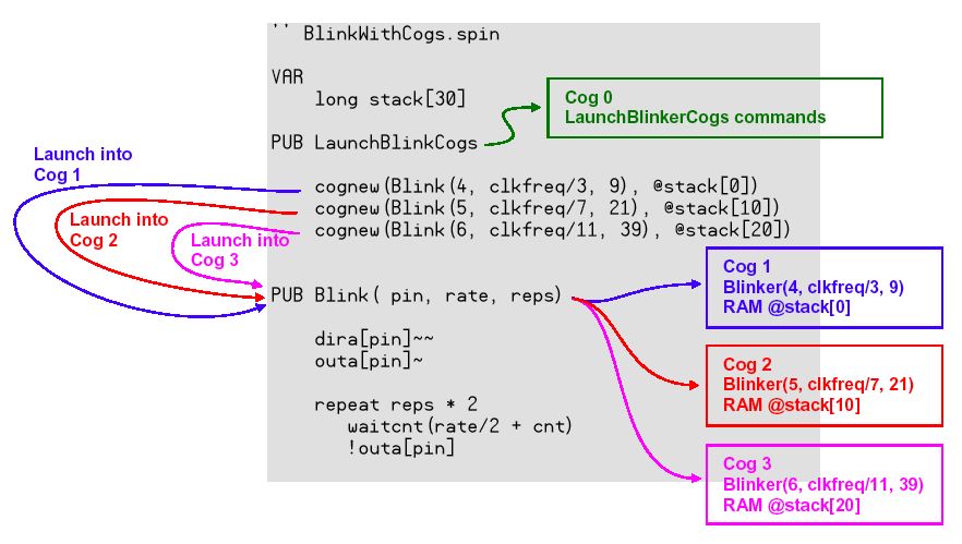
Because Cog(0) doesn't have the statement any longer in this example when three Cogs is started by three statements, it shuts down here. It shuts down because there is not Cog that observes the return when the other three Cogs also ends each REPEAT loop either. If the processing of the last Cog ends, Propeller becomes Low Power Mode. However, an infinite loop is sure to continue without entering this state when the embedded system is made.
Other Cogs that executes the spin method should have the return address of my method call, the local variable, and the middle operation expression until Cog(0) accesses and stores unused global RAM. The temporary storage area secured for global RAM is called stack space, and, for this, it defines it as stack. The Long array of 30 elements was secured by describing long stack30 in the example above. The list of the memory of Propeller Tool, and it is a blue area, and first part of unused RAM that Cog(0) uses as own stack. When the fraction dashes out, the stack area is the following ..each of four Longs(16bytes).. the first part.
For instance, COGNEW command (The argument is 2(the method and stack)) that appears here :. In the following cases, I have not understood which actually Cog it is until executing it because it allocates Cog by which Propeller has automatically become empty next.
cognew(Blink(4, clkfreq/3, 9), @stack[0]) COGINIT command (The argument is 3(the Cog specification, the method, and stack)) is executed, and however, it is, and this can execute Cog(6) by doing as follows specifying it.
coginit(6, Blink(4, clkfreq/3, 9), @stack[0]) I think that here is refreshing as a programming. However, when COGINIT is executed according to the reference manual because there was no return value it, starting some processes already seem to be canceled.
How to use, and when COGSTOP command (one of the ..argument.. Cog specification), and Cog is made to be stopped, it becomes the following.
cogstop(Cog) In the example of the treatment so far because the specification of Cog is necessary for this for specification STOP was done by storing Cog ID that was the return value of COGNEW in the global variable when COGNEW was done and "ID of Cog that had become empty" was acquired, and using it. However, I do not think that it is too bad to fix Cog ID in all the processes specifying it either.
It explains details of stack whose even here was a mystery in the text following this. It is said that the following areas are needed respectively when stack is called. A very inarticulate reason is that it is not a fixed length but it is variable-length up to now.
- 2 - return address
- 1 - return result
- number of method parameters
- number of local variables
- workspace for intermediate expression calculations
It becomes as follows if it is stack for calling "Blink(pin, rate, reps)" as one example, and stack of 10Longs is needed.
- 2 - return address
- 1 - return parameter
- 3 - pin, freq, and reps parameters
- 1 - time local variable
- 3 - workspace for calculations.
It is said that this depends on the following rules accurately. Is it good for the time being in 10Longs or 12Longs because it is troublesome?
STEP 1: As you develop your object, provide a large amount of stack space for any Spin code launched via COGINIT or COGNEW. Simple code may take around 8 longs, but more complex code may take hundreds of longs. Start with a large value,128 longs for example, and increase it as needed to ensure proper operation.STEP 2: When your object's development is complete, include this object ("Stack Length") within it and call Init before launching any Spin code. NOTE: For the Init's parameters, make sure to specify the proper address and length (in longs) of the stack space you actually reserved.
		Example:
		VAR
			long Stack[128]
		OBJ
			Stk : "Stack Length"
		PUB Start
			Stk.Init(@Stack, 128)				'Initialize Stack for measuring later
			cognew(@MySpinCode, @Stack)			'Launch code that utilizes Stack
STEP 3: Fully exercise your object, being sure to affect every feature that will cause the greatest nested method calls and most complex set of run-time expressions to be evaluated. This may have to be a combination of hard-coded tests and physical, external stimuli depending on the application.
STEP 4: Call GetLength to measure the stack space actually utilized. GetLength will return a pointer to a result string and will serially transmit the results on the TxPin at the BaudRate specified. Use 0 for BaudRate if no transmission is desired. The value returned in the string will be -1 if the test was inconclusive (try again, but with more stack space reserved), 0 if the stack was never used, or some other value indicating the maximum utilization (in longs) of your stack up to that moment in time.
		Example:  If the application uses an external 5 MHz resonator and its clock settings are as follows:
		CON
			_clkmode = xtal1 + pll16x
			_xinfreq = 5_000_000
		{{ Then the following line will transmit "Stack Usage: #" on I/O pin 30 (the Tx pin normally
			used for programming) at 19200 baud; where # is the utilization of your Stack. }}
			Stk.GetLength(30, 19200)
STEP 5: Set your reserved Stack space to the measured size and remove this object, Stack Length, from your finished object.
The reserved word of the name of stack here is nothing. Even what symbol it is, used as stack if it secures for VAR block, and it gives it as a parameter by the "@" sign with the COGNEW command and the COGINIT command. Moreover, the spin language has internally reserved the symbol of "_stack". This is space for the stack for the method at the Top level to call Cog(0). Therefore, this symbol cannot be used without permission.
Next, it explained Return Parameter by the following figures. There was a method of describing the return value and the local variable of the method at the same time as a harvest that not was so far.
PUB ButtonTime(pin) : dt | t1, t2t It only has to make it to the way above. This is first written after the colon because the return value is one, it puts a comma in addition after the pipe, and many local variables are defined.
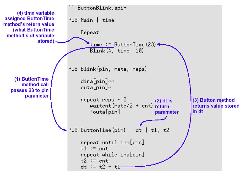
There is a reserved word of the name of the variable result in the spin language though it appeared in the tutorial of the Propeller manual. As for this, the return value automatically enters here when the method ends even if the return value is not defined the following, and specifying it.
PUB ButtonTime(pin) | t1, t2 		' Optional return parameter local var name removed
	repeat until ina[pin]
	t1 := cnt
	repeat while ina[pin]
	t2 := cnt
	result := t2 - t1 			' Value stored by result is automatically returned
It is separately written that the return value is recommended to be defined specifying it because you may use result. The last continuing topic is Cog ID Indexing Because Cog ID started by COGNEW returns as return value (result) of COGNEW, this can be used for the following COGSTOP as global variable, and it use it for the use state tracking of Cog.
---Whether Cogs was able to be mastered by this well or not? Yesterday decided to remodel, and to experiment on exp004.spin that can execute the task "Video display output, LED port output, and switch input". When it is re-[**], it is following.
{{ exp004.spin }}

CON
	_clkmode = xtal1 + pll16x
	_xinfreq = 5_000_000
	MAXLEDS = 6 'Number of LED objects to use

OBJ
	Num : "Numbers"
	TV : "TV_Terminal"
	LED[6] : "Output"

PUB Main | Temp, dummy
	Num.Init                      'Initialize Numbers
	TV.Start(12)                  'Start TV Terminal
	Temp := 1000
	TV.Str(string("start "))
	TV.Str(Num.ToStr(Temp, Num#DEC))                     'its result in decimal
	TV.Out(",")

	dira[16..23]~~ 'Set pins to outputs
	LED[NextObject].Start(16, 50, 0)
	LED[NextObject].Start(16, 1000, 0)

	dira[0..2]~                                         ' Set to Input (redundant)
	dummy := ina[0] + ina[1] + ina[2]
	repeat
		outa[18] := ina[0]
		outa[19] := ina[1]
		outa[20] := ina[2]
		if dummy <> ina[0] + ina[1] + ina[2]
			dummy := ina[0] + ina[1] + ina[2]
			Temp++
			TV.Str(Num.ToStr(Temp, Num#DEC))
			TV.Out(",")

PUB NextObject : Index
	repeat
		repeat Index from 0 to MAXLEDS-1
			if not LED[Index].Active
				quit
	while Index == MAXLEDS
And, this exp004.spin calls Output.spin as an external target. When it is re-[**], it is following. this
{{ Output.spin }}

VAR
	long Stack[9]
	byte Cog

PUB Start(Pin, DelayMS, Count): Success
	Stop
	Success := (Cog := cognew(Toggle(Pin, Delay, Count), @Stack) + 1)

PUB Stop
	if Cog
	cogstop(Cog~ - 1)

PUB Active: YesNo
	YesNo := Cog > 0

PUB Toggle(Pin, DelayMS, Count)
	dira[Pin]~~
	repeat
		!outa[Pin]
		waitcnt(clkfreq / 1000 * DelayMS + cnt) 		'Wait for DelayMS
	while Count := --Count #> -1
	Cog~
It was noticed that there was a bug for a moment though it moved for the time being when often seeing. First of all, dira 16..23 ~~ "Set pins to outputs" that existed in Main of exp005.spin was erased because it was unnecessary. It is output dir set of the port because of being in the Toggle method in Output.spin.
Exp005.spin was corrected on that as follows. Two Cog was called for the time being in the place where the video outlet was initialized for the LED blinking processing to examine the appearance of Cog, and the return value was displayed.
{{ exp005.spin }}

CON
	_clkmode = xtal1 + pll16x
	_xinfreq = 5_000_000
	MAXLEDS = 6 'Number of LED objects to use

OBJ
	Num : "Numbers"
	TV : "TV_Terminal"
	LED[6] : "Output"

PUB Main | Temp, dummy
	Num.Init                      'Initialize Numbers
	TV.Start(12)                  'Start TV Terminal
	TV.Str(string("start "))

	Temp := LED[NextObject].Start(16, 50, 0)
	TV.Str(Num.ToStr(Temp, Num#DEC))
	TV.Out(",")

	Temp := LED[NextObject].Start(16, 1000, 0)
	TV.Str(Num.ToStr(Temp, Num#DEC))
	TV.Out(",")

	dira[0..2]~                   ' Set to Input (redundant)
	dummy := ina[0] + ina[1] + ina[2]
	repeat
		outa[18] := ina[0]
		outa[19] := ina[1]
		outa[20] := ina[2]
		if dummy <> ina[0] + ina[1] + ina[2]
			dummy := ina[0] + ina[1] + ina[2]
			Temp++
			TV.Str(Num.ToStr(Temp, Num#DEC))
			TV.Out(",")

PUB NextObject : Index
	repeat
		repeat Index from 0 to MAXLEDS-1
			if not LED[Index].Active
			quit
	while Index == MAXLEDS
Then, the result was neither 1, not 2, and the video display always became "4, 5, ---". The return value of the first Start method becomes and four becomes Cog(3) because it does +1 return value. In a word, if it is Cog(0), three Cog in total will already have been started from Cog(1) to Cog(2) at the stage where "TV.Start(12)" of the video outlet was executed as for running with Main. With this, because the Cog check in Output.spin did not have the meaning so much, both united, and were seen as following exp006.spin.
{{ exp006.spin }}

CON
	_clkmode = xtal1 + pll16x
	_xinfreq = 5_000_000

VAR
	long Stack[80]

OBJ
	Num : "Numbers"
	TV : "TV_Terminal"

PUB Main | Temp, dummy
	Num.Init
	TV.Start(12)
	TV.Str(string("Propellar " , "start "))

	Temp := cognew(Toggle(16, 50, 0), @Stack[0])
	TV.Str(Num.ToStr(Temp, Num#DEC))
	TV.Out(",")
	Temp := cognew(Toggle(16, 1000, 0), @Stack[10])
	TV.Str(Num.ToStr(Temp, Num#DEC))
	TV.Out(",")
	Temp := cognew(Toggle(17, 100, 0), @Stack[20])
	TV.Str(Num.ToStr(Temp, Num#DEC))
	TV.Out(",")
	Temp := cognew(Toggle(17, 1000, 0), @Stack[30])
	TV.Str(Num.ToStr(Temp, Num#DEC))
	TV.Out(",")
	Temp := cognew(Toggle(18, 200, 0), @Stack[40])
	TV.Str(Num.ToStr(Temp, Num#DEC))
	TV.Out(",")
	Temp := cognew(Toggle(18, 1000, 0), @Stack[50])
	TV.Str(Num.ToStr(Temp, Num#DEC))
	TV.Out(",")

	dira[0..2]~
	dummy := ina[0] + ina[1] + ina[2]
	repeat
		outa[18] := ina[0]
		outa[19] := ina[1]
		outa[20] := ina[2]
		if dummy <> ina[0] + ina[1] + ina[2]
			dummy := ina[0] + ina[1] + ina[2]
			Temp++
			TV.Str(Num.ToStr(Temp, Num#DEC))
			TV.Out(",")

PUB Toggle(Pin, DelayMS, Count)
	dira[Pin]~~
	repeat
		!outa[Pin]
		waitcnt(clkfreq / 1000 * DelayMS + cnt)
	while Count := --Count #> -1
Then, the video display of the result became "3. 4, 5, 6, 7, -1, ---". It failed in the last COGNEW, -1 returned, and it became "0, 1, 2, ---" because of the switch operation. Still, Cog(1) and Cog(2) work by Main for Cog(0) and the video outlet.
Wednesday 12th, March 2008
The following were made because it had hit on from the experiment for a moment.{{ exp007.spin }} CON _clkmode = xtal1 + pll16x _xinfreq = 5_000_000 VAR long Stack[80] OBJ Num : "Numbers" TV : "TV_Terminal" PUB Main | Temp, dummy Num.Init TV.Start(12) TV.Str(string("Propellar " , "start ")) Temp := cognew(Toggle(16, 50, 0), @Stack[0]) TV.Str(Num.ToStr(Temp, Num#DEC)) TV.Out(",") Temp := cognew(Toggle(16, 1000, 0), @Stack[10]) TV.Str(Num.ToStr(Temp, Num#DEC)) TV.Out(",") Temp := 5 dira[0..2]~ dira[18..20]~~ dummy := ina[0] + ina[1] + ina[2] repeat outa[18..20] := ina[0..2] if dummy <> ina[0] + ina[1] + ina[2] dummy := ina[0] + ina[1] + ina[2] cogstop(Temp) TV.Str(Num.ToStr(Temp, Num#DEC)) TV.Out(",") Temp := ++Temp & %00000111 PUB Toggle(Pin, DelayMS, Count) dira[Pin]~~ repeat !outa[Pin] waitcnt(clkfreq / 1000 * DelayMS + cnt) while Count := --Count #> -1If this program has a switch pushed, it will stop Cog specified by Temp. The increment of the value of Temp is carried out from an initial value, and it returns to the next of 7 at zero. Since Cog (0) is main processing, so to speak, it is "suicidal-explosion" program. And although it consisted of Cog (5) here, this was variously changed by Propeller Editor, and by F10, it compiled and performed and experimented. The following are the results. A rough point became a result the same as the expectation.
- Initial value = 5
The video is displayed as unpalatable "3, 4, ", and LED of P16 does the intermittent lighting operation (repetition of high-speed blinking for one second and light/one second). "6, " and the video are displayed when "5, " and the video are displayed when the switch is pushed, LED lights, and the switch is separated and LED is turned off. The change ..video display.. disappears though "7, " and the video are displayed when the switch is pushed and * and LED are turned off when LED separates lighting and the switch. Anything doesn't occur even if the switch is operated after this. - It is because Main had ended because Cog(0) was stopped with [notokoro]. The intermittent lighting operation of LED of P16 continues for a long time because Cog(3) and Cog(4) are alive of it.- Initial value = 6
It is first indicated by video with "3 and 4", and LED of P16 is carrying out intermittent lighting operation. If a switch is pushed, it will be indicated by video with "6", and if LED detaches lighting and a switch, it will be indicated by video with "7" and LED will put out the light. If a switch is pushed, * and LED will not be turned on, either but no change also of a video display will be lost. Even if it operates a switch, nothing stops occurring after this. * It is the mystery which LED does not turn on but since Cog (0) was stopped by the way, and Main has been completed just for a moment. Since Cog (3) and Cog (4) are valid, intermittent lighting operation of LED of P16 continues all the time.- Initial value = 7
The video is displayed as unpalatable "3, 4, ", and LED of P16 does the intermittent lighting operation. The change ..video display.. disappears though "7, " and the video are displayed when the switch is pushed and * and LED are turned off when LED separates lighting and the switch. Anything doesn't occur even if the switch is operated after this. - It is because Main had ended because Cog(0) was stopped with [notokoro]. The intermittent lighting operation of LED of P16 continues for a long time because Cog(3) and Cog(4) are alive of it.- Initial value = 0
The video is displayed as unpalatable "3, 4, ", and LED of P16 does the intermittent lighting operation. Neither * nor LED light when the switch is pushed, and the change disappears as for any video display. Anything doesn't occur even if the switch is operated after this. - It is a mystery that LED doesn't light though it is because Main had ended because it stopped [de] Cog(0) for a moment. The intermittent lighting operation of LED of P16 continues for a long time because Cog(3) and Cog(4) are alive of it.- Initial value = 1
The video is displayed as unpalatable "3, 4, ", and LED of P16 does the intermittent lighting operation. - and LED light when the switch is pushed, and the video screen disappears. Anything doesn't occur even if LED is turned off when the switch is separated, and the switch is operated after this. - This seems to do important operation to the video display when Cog(1) is stopped with [notokoro], and the video disappears. Because Cog(0) is alive here, even the following switch input ˘ŞLED turning off is executed.- Initial value = 2
The video is displayed as unpalatable "3, 4, ", and LED of P16 does the intermittent lighting operation. - and LED light when the switch is pushed, and the change disappears as for any video display. Anything doesn't occur even if the switch is operated after this. - Nothing was done though the video display was alive when Cog(2) was stopped with [notokoro].- Initial value = 3
The video is displayed as unpalatable "3, 4, ", and LED of P16 does the intermittent lighting operation. When the switch was pushed, "3, " and the video were displayed, LED lit, and LED of P16 became blinking every one second. "4, " and the video were displayed when the switch was separated, LED disappeared, and P16 also disappeared. "5, " and the video are displayed when the switch is pushed and LED lights. "6, " and the video were displayed when the switch was separated and LED disappeared. The change ..video display.. disappears though "7, " and the video are displayed when the switch is pushed and LED is turned off when LED separates lighting and the switch. Anything doesn't occur even if the switch is operated after this. Because Cog(3) stops with the first switch ON, and Cog(4) stopped next.- Initial value = 4
The video is displayed as unpalatable "3, 4, ", and LED of P16 does the intermittent lighting operation. When the switch was pushed, "4, " and the video were displayed, LED lit, and one became a high-speed blinking as for LED of P16. P16 is this state after this for a long time. "5, " and the video were displayed when the switch was separated and LED disappeared. "6, " and the video were displayed when the switch was pushed, "7, " and the video were displayed when LED separated the lighting switch, and LED disappeared. Anything doesn't occur to the video display even if the change disappears, and the switch is operated after this. Because Cog(4) stopped with the first switch ON.Moreover, the option for the video display was excavated. It is easy to display information at a specific position in the screen if there are a home, changing line, and a tab though the cursor coordinates cannot be given. Using TV : "TV_Terminal" define - As for the rest, it is as follows though from $20 to $7E is a usual character by the hexadecimal when experimenting.
- TV.Out($00 ) - home
- TV.Out($01 ) - The character color is white (default).
- TV.Out($02 ) - If the background color is a black, the character color is green.
- TV.Out($03 ) - If the background color is a black, the character color is red.
- TV.Out($04 ) - The background color of the screen is black (default).
- TV.Out($05 ) - Blue and the character color : the background color of the screen. "White + background color"
- TV.Out($06 ) - Green and the character color : the background color of the screen. "White + background color"
- TV.Out($07 ) - Red and the character color : the background color of the screen. "White + background color"
- TV.Out($09 ) - Tab
- TV.Out($0D ) - return
Well, it decided to advance to the world of hardness and the assembler more and more in the place where the tool of video outlet that monitored the processing of Propeller had been obtained. A lot of object libraries that the engineer of the Parallax Co. not only was offered to the site of Propeller but also all over the world curious was tried Propeller and had made were put. After all, anxious in that was nether information.
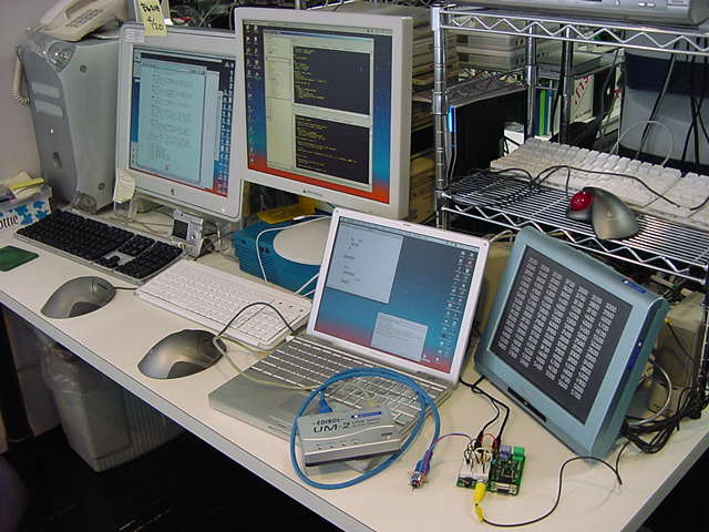
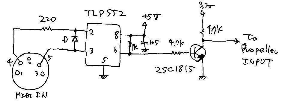
MIDI in object for Propeller It was very Propeller, and there was already a person who had made the library of the MIDI input. The project that became a motive is the following according to developer's Mr. Tom Dimock.
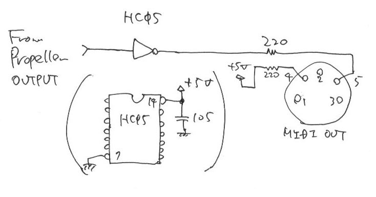
This object was created as part of my project to equip my Austin Pipe Organ to play from a MIDI stream. I acquired the organ about twenty years ago, when the church that owned it decided to replace it with an electronic organ after the pipe organ was damaged in a flood. I worked with a close friend to build a MIDI controller for it based on the 8051 micro-computer. I etched my own circuit boards and we actually got it all working - one of the first MIDI capable pipe organs in the world. But the system did not age well, and was difficult to impossible to modify. Several years ago the organ stopped playing. I had been looking at several possibilities for building a new controller - the Javelin chip from Parallax looked very promising (I was a Java programmer at work), until I found that it could not deal with the 31.25KB baud rate of MIDI. The SX processors could have done the job, and I was starting to look into them when the Propeller chip was announced. The organ now plays from my breadboard implementation, and I should have my ProtoBoard version up and running very soon.Still, it was not usual. The schematic diagram that exists in the document cannot get this for a moment as the person in question also is writing as follows though is the following.I'm pretty sure that you could reduce the 5v connection to the opto-isolator to 3.3v and eliminate the 1K resistor, but I have not tried that.The voltage of 3.3V or more hangs to the input pin of Propeller, and there is danger of destroying it.
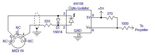
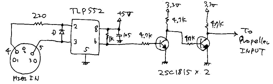
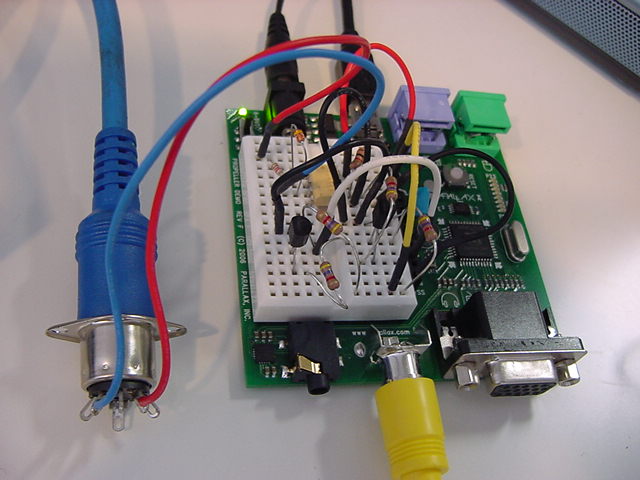
Then, it received to two steps (reversed of reversing) with 2SC1815 for usual photo coupler TLP552 and the voltage level shift at hand, and it saw as the first of all following schematic diagrams.
MidiIn.spin Library MidiIn.spin was called without arranging one's verbs and objects at all up, and the following programs were made. Because the processing of the switch input and blinking LED is already a confirmed operation I will hour by hour monitor the data as a video display when there is MIDI input.
{{ exp008.spin }}

CON
	_clkmode = xtal1 + pll16x
	_xinfreq = 5_000_000

OBJ
	Num : "Numbers"
	TV : "TV_Terminal"
	midiIn : "MidiIn"

PUB Main | Temp, dummy
	Num.Init
	TV.Start(12)
	TV.Str(string("Propellar " , "start "))
	midiIn.start(7, 3)
	repeat
		dummy := midiIn.evtCheck
		if dummy <> -1
			Temp := midiIn.evt
			TV.Str(Num.ToStr(Temp, Num#HEX))
			TV.Out(" ")
When details sent MIDI in the uncertainty then, the video was able to be displayed by what being received. The following are the patterned photographs. The video signal united by this with the hardness of the MIDI signal and the software of Propeller. It will have moved as a cooperated about the spin language and the Propeller assembler the first sample because MidiIn.spin of the called external object was written by the assembler.
ˇˇ
ˇˇ
Thursday 13th, March 2008
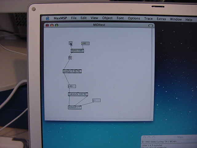
This decided to be changed little by little as follows, to understand while trying, and to improve it as a software parts of my own way though it moved for the time being because it doesn't understand at all when attaching. MidiIn.spin I duplicated "008" and renamed it to "009". I reproduced "MidiIn" and renamed it "MidiIn01" likewise. The reason is because it is necessary to cope in one called one to call. And it decided to approach the important part of a program, checking deleting an unnecessary portion in one hand from MidiIn01 little by little little by little, and becoming it with equivalent operation about a Propeller manual, one by one. probably, there is only this for the time being, in order to fill both of "the first CPU that has not got used to come out", and "analyzing others' program."It was a thing that the operation thought to be "MIDI has been received" seemed to receive the MIDI message apparently only once every two times that noticed first. It is a result of trying some with Max/MSP on the MIDI sending side. There was a bug in the following parts as a result of examining it.
		dummy := midiIn.evtCheck
		if dummy <> -1
			Temp := midiIn.evt
			TV.Str(Num.ToStr(Temp, Num#HEX))
When the return value was not -1, the return value was already MIDI receive data when the source was often read though going to have assumed that the following method was called because the method was called, and there was data if this return value was not -1. The method was the one that it is made to wait until new MIDI data came in the opposite. Then, all MIDI was safely received by changing as follows and it came to display the video.
		dummy := midiIn.evtCheck
		if dummy <> -1
			TV.Str(Num.ToStr(dummy, Num#HEX))
The following matters were arranged while confirming it by the experiment examining it like this.
- In Cog in the Propeller processor, there is no one that corresponds to the register of usual CPU. All RAM areas in Cog are the one like the register. The memory of the specified address becomes a storage location operand as it is, and the specified address is made an immediate operand as it is.
- The global variable defined in VAR block is a meaning named global in the Cog shared by each method of each object. Even if the global variable of the same by chance symbol is defined in VAR block of other object (for instance, cog), it is irrelevant. Whether to have acquired the variable in other object, it is necessary to define the method of returning the value and to call it.
- "Cog ID + 1" returns mostly when the start method of initialization is called for a new object. There may not be [maa;kore] by you though stop is mostly called in start.
- Data and the Propeller assembler code are described in DAT block. ORG directive is put on the head of DAT block. It starts by NEWCOG putting "@" on the label of the initial address in this block. FIT directive is put at the end of DAT block. As a result, the compiler examines whether to enter Propeller internal RAM.
- The mark of "0-0" of storing the numerical value in the variable by the long instruction is to be buried by all 0 only, it is the same as "0". Because "RES" is partitioning (reserve) of the long variable, alone, the numerical value has not been initialized (irregularity).
- The binary expression is "%01100011" etc. The hexadecimal expression is "$013F007F" etc.
- Two-line pair such as "test eventEnable,doNoteOn wz" and "if_z mov ignoreNoteOn,#0" is "If 0 flags stand, value # 0 is stored in variable ignoreNoteOn. " of doing "The bit of the doNoteOn bit of variable eventEnable is tested, and the result is stored in 0 flags".
- The label can be freely defined in global assuming that the head starts by "_" or the character excluding the reserved word. To make it to a local label, ":" is put on the head. The label is used by JMP, CALL, and COGINIT.
- Meaning that "#" specifies the value as it is. When it is "jmp some_labal", it becomes, and it becomes it , saying that "jmp #some_labal" and "Fly to some_labal and the place where the label definition was done" , saying that "Fly to the address of contents of the global variable defined as some_labal".
- In Propeller, the divergence jump JMP in not the subroutine call basic CALL but the jump table is used. It is said that the label "Address _ ret of the subroutine" is necessary for the place of return " RET" as it is a charm when the subroutine is called by all means by CALL. Because here is important, let's examine it which.. tidying sooner or later.
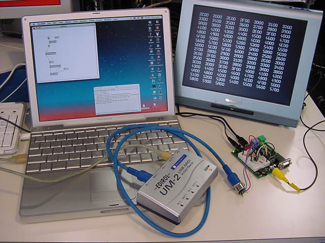
Even the following combinations were able to be done simply as a result of a variety of trying. The video can be neatly displayed by the hexadecimal display by receiving a usual MIDI event by this.
{{ exp009.spin }}

CON
	_clkmode = xtal1 + pll16x
	_xinfreq = 5_000_000

OBJ
	Num : "Numbers"
	TV : "TV_Terminal"
	midiIn : "MidiIn01"

PUB Main | dummy
	Num.Init
	TV.Start(12)
	TV.Str(string("Propellar " , "Start! "))
	TV.Str(string("MidiIn Cog ="))
	dummy := midiIn.start(7)
	TV.Str(Num.ToStr(dummy, Num#DEC))
	repeat
		dummy := midiIn.eve
		if dummy <> -1
			TV.Str(Num.ToStr(dummy, Num#HEX9))
It is displayed when starting as "MidiIn Cog = 4". Cog(1) and Cog(2) are used for Main for Cog(0) and the video outlet. It is because +1 value 4 that is used Cog(3) because of the initialization of the MIDI input, and is done has returned.
VAR
	long  eventHead , eventTail
	long  eventBuffer[32]

PUB start(_midiPin) : okay
	midiPin      := _midiPin
	event_head   := @eventHead
	event_tail   := @eventTail
	event_buffer := @eventBuffer
	bitticks     := clkfreq / 31_250
	halfticks    := bitticks / 2
	longfill(@eventHead,34,0)
	okay := cognew(@entry, 0) + 1

PUB eve : event
	event := -1
	if eventTail <> eventHead
		event := eventBuffer[eventTail]
		eventTail := (eventTail + 1) & $0F

DAT
		org

entry		mov     midiMask,#1
		shl     midiMask,midiPin
		mov     nextDataHandler,#getMidiByte

getMidiByte             waitpne midiMask,midiMask
                        mov     midiBits,#9
                        mov     bitClk,cnt
                        add     bitClk,halfticks
                        add     bitClk,bitticks

:midiBit                waitcnt bitClk,bitticks
                        test    midiMask,ina            wc
                        rcr     midiByte,#1
                        djnz    midiBits,#:midiBit

                        shr     midiByte,#32-9
                        and     midiByte,#$FF
                        test    midiByte,#$80           wz
              if_z      jmp     nextDataHandler
                        mov     t1,midiByte
                        and     t1,#$F8
                        cmp     t1,#$F8                 wz
              if_z      jmp     #getMidiByte
                        mov     eventHandler,#getMidiByte
                        mov     command,midiByte
                        shr     command,#4
                        mov     channel,midiByte
                        and     channel,#$0F
                        shl     channel,#16
                        mov     t1,command
                        and     t1,#$07
                        add     t1,#:cmdTable
                        jmp     t1
:cmdTable               jmp     #noteOffCmd
                        jmp     #noteOnCmd
                        jmp     #aftertouchCmd
                        jmp     #controllerCmd
                        jmp     #programChangeCmd
                        jmp     #channelPressureCmd
                        jmp     #pitchWheelCmd

writeEvent              rdlong  t1,event_head
                        mov     event_offset,t1
                        shl     event_offset,#2
                        add     event_offset,event_buffer
                        wrlong  event_data,event_offset
                        add     t1,#1
                        and     t1,#$0F
                        wrlong  t1,event_head
writeEvent_ret          ret

noteOnCmd               mov     nextDataHandler,#note
                        mov     eventHandler,#noteOn
                        jmp     #getMidiByte
noteOffCmd              mov     nextDataHandler,#note
                        mov     eventHandler,#noteOff
                        jmp     #getMidiByte
aftertouchCmd           mov     nextDataHandler,#note
                        mov     eventHandler,#aftertouch
                        jmp     #getMidiByte
controllerCmd           mov     nextDataHandler,#cont_num
                        mov     eventHandler,#controller
                        jmp     #getMidiByte
programChangeCmd        mov     nextDataHandler,#program_num
                        mov     eventHandler,#programChange
                        jmp     #getMidiByte
channelPressureCmd      mov     nextDataHandler,#channel_pressure
                        mov     eventHandler,#channelPressure
                        jmp     #getMidiByte
pitchWheelCmd           mov     nextDataHandler,#pitch_wheel_lo
                        mov     eventHandler,#pitchWheel
                        jmp     #getMidiByte

note                    mov     noteValue,midiByte
                        shl     noteValue,#8
                        mov     nextDataHandler,#velocity
                        jmp     #getMidiByte
velocity                mov     velocityValue,midiByte
                        mov     nextDataHandler,#note
                        jmp     eventHandler
cont_num                mov     controllerNumber,midiByte
                        shl     noteValue,#8
                        mov     nextDataHandler,#cont_val
                        jmp     #getMidiByte
cont_val                mov     controllerValue,midiByte
                        mov     nextDataHandler,#cont_num
                        jmp     eventHandler
program_num             mov     programValue,midiByte
                        jmp     eventHandler
channel_pressure        mov     channelPressureValue,midiByte
                        jmp     eventHandler
pitch_wheel_lo          mov     pitchWheelLoValue,midiByte
                        mov     nextDataHandler,#pitch_wheel_hi
                        jmp     #getMidiByte
pitch_wheel_hi          mov     pitchWheelHiValue,midiByte
                        shl     noteValue,#7
                        mov     nextDataHandler,#pitch_wheel_lo
                        jmp     eventHandler

noteOn                  mov     event_data,noteOnEvt
                        or      event_data,channel
                        or      event_data,noteValue
                        or      event_data,velocityValue
                        call    #writeEvent
                        jmp     #getMidiByte
noteOff                 mov     event_data,noteOffEvt
                        or      event_data,channel
                        or      event_data,noteValue
                        or      event_data,velocityValue
                        call    #writeEvent
                        jmp     #getMidiByte
aftertouch              mov     event_data,aftertouchEvt
                        or      event_data,channel
                        or      event_data,noteValue
                        or      event_data,velocityValue
                        call    #writeEvent
                        jmp     #getMidiByte
controller              mov     event_data,controllerEvt
                        or      event_data,channel
                        or      event_data,controllerNumber
                        or      event_data,controllerValue
                        call    #writeEvent
                        jmp     #getMidiByte
programChange           mov     event_data,programChangeEvt
                        or      event_data,channel
                        or      event_data,programValue
                        call    #writeEvent
                        jmp     #getMidiByte
channelPressure         mov     event_data,channelPressureEvt
                        or      event_data,channel
                        or      event_data,channelPressureValue
                        call    #writeEvent
                        jmp     #getMidiByte
pitchWheel              mov     event_data,pitchWheelEvt
                        or      event_data,channel
                        or      event_data,pitchWheelHiValue
                        or      event_data,pitchWheelLoValue
                        call    #writeEvent
                        jmp     #getMidiByte

noteOnEvt               long    $00000000
noteOffEvt              long    $01000000
aftertouchEvt           long    $02000000
controllerEvt           long    $03000000
programChangeEvt        long    $04000000
channelPressureEvt      long    $05000000
pitchWheelEvt           long    $06000000
bitticks                long    0
halfticks               long    0
midiPin                 long    0
event_head              long    0
event_tail              long    0
event_buffer            long    0
t1                      res     1
event_offset            res     1
event_data              res     1
midiMask                res     1
midiBits                res     1
bitClk                  res     1
midiByte                res     1
nextDataHandler         res     1
eventHandler            res     1
rtEventHandler          res     1
command                 res     1
channel                 res     1
noteValue               res     1
velocityValue           res     1
controllerNumber        res     1
controllerValue         res     1
programValue            res     1
channelPressureValue    res     1
pitchWheelLoValue       res     1
pitchWheelHiValue       res     1

                        fit
Friday 14th, March 2008
As for the Propeller assembler, the sample program that moved for the time being was only "Move for the time being (It is possible to use it). " yesterday though is original the main side no understanding of actual operation. Then, to understand the operation of the Propeller assembler and Cog further, this inside decided to be run after more in detail. And, the bug was immediately found. HTML manualsaid that "I only have a 16 slot event buffer, with no provision for handling buffer overflow."VAR long eventHead , eventTail long eventBuffer[32] PUB start(_midiPin) : okay midiPin := _midiPin event_head := @eventHead event_tail := @eventTail event_buffer := @eventBuffer bitticks := clkfreq / 31_250 halfticks := bitticks / 2 longfill(@eventHead,34,0) okay := cognew(@entry, 0) + 1 PUB eve : event event := -1 if eventTail <> eventHead event := eventBuffer[eventTail] eventTail := (eventTail + 1) & $0F --- writeEvent rdlong t1,event_head mov event_offset,t1 shl event_offset,#2 add event_offset,event_buffer wrlong event_data,event_offset add t1,#1 and t1,#$0F wrlong t1,event_head writeEvent_ret retThis is contradicted for a moment. If MIDI [ibentokyu-baffa] is 16 slots, it is following.
VAR
	long  eventHead , eventTail
	long  eventBuffer[16]

PUB start(_midiPin) : okay
	midiPin      := _midiPin
	event_head   := @eventHead
	event_tail   := @eventTail
	event_buffer := @eventBuffer
	bitticks     := clkfreq / 31_250
	halfticks    := bitticks / 2
	longfill(@eventHead,18,0)
	okay := cognew(@entry, 0) + 1

PUB eve : event
	event := -1
	if eventTail <> eventHead
		event := eventBuffer[eventTail]
		eventTail := (eventTail + 1) & $0F

---

writeEvent	rdlong  t1,event_head
			mov     event_offset,t1
			shl     event_offset,#2
			add     event_offset,event_buffer
			wrlong  event_data,event_offset
			add     t1,#1
			and     t1,#$0F
			wrlong  t1,event_head
writeEvent_ret	ret
It moved neatly without trouble when changing like this. And, if MIDI [ibentokyu-baffa] is 32 slots, it is following.
VAR
	long  eventHead , eventTail
	long  eventBuffer[32]

PUB start(_midiPin) : okay
	midiPin      := _midiPin
	event_head   := @eventHead
	event_tail   := @eventTail
	event_buffer := @eventBuffer
	bitticks     := clkfreq / 31_250
	halfticks    := bitticks / 2
	longfill(@eventHead,34,0)
	okay := cognew(@entry, 0) + 1

PUB eve : event
	event := -1
	if eventTail <> eventHead
		event := eventBuffer[eventTail]
		eventTail := (eventTail + 1) & $1F

---

writeEvent	rdlong  t1,event_head
			mov     event_offset,t1
			shl     event_offset,#2
			add     event_offset,event_buffer
			wrlong  event_data,event_offset
			add     t1,#1
			and     t1,#$1F
			wrlong  t1,event_head
writeEvent_ret	ret
It moved neatly without trouble though it changed like this. Then, as the person in question also is writing It is a thing that the bug remains in the open to the public program. It was relieved for a moment.
Well, it came to the place where it finally challenged one of the cores. MIDI information is handled. Propeller doesn't include UART (special chip) etc. for serial communications. It is a thing that it will be able to do also with the cereal and the video only in the software of Cog. It thinks even about the start bit or the stop bit by coming back even to the format of the MIDI signal, and, because, it is after a long time.
Program..only..really..numerical value..definition..as follows.
	bitticks     := clkfreq / 31_250
	halfticks    := bitticks / 2
Because because state of cereal signal is sampled with more high-speed software and value is examined, edge of change point is made starting point, and value of midway point of "Half of width in bits" is assumed to be value of the bit It is at the following that it seeming is an assembler routine and be it for the time being.
entry		mov     midiMask,#1
		shl     midiMask,midiPin
		mov     nextDataHandler,#getMidiByte

getMidiByte	waitpne midiMask,midiMask
		mov     midiBits,#9
		mov     bitClk,cnt
		add     bitClk,halfticks
		add     bitClk,bitticks

:midiBit	waitcnt bitClk,bitticks
		test    midiMask,ina            wc
		rcr     midiByte,#1
		djnz    midiBits,#:midiBit

		shr     midiByte,#32-9
		and     midiByte,#$FF
		test    midiByte,#$80           wz
	if_z      jmp     nextDataHandler
In short, all infinite loops of Cog(3) jump to "getMidiByte" after initialization. First of all, one is substituted for midiMask as follows immediately after entry.
mov midiMask,#1And, only the numerical value of the input pin shifts this as follows left.
shl midiMask,midiPinIn a word, "Value from which one stands only at the bit position of the input pin" is midiMask. And, contents of nextDataHandler become # getMidiByte for the time being as follows depending, too.
mov nextDataHandler,#getMidiByteWhen three byte message of MIDI is received distinguishing, contents of this nextDataHandler are changed. Well, processing by essential getMidiByte is the following.
waitpne midiMask,midiMaskThere is a format of waitpne with waitpne State, Mask. INA command of spin seems to be able to take all of the 32 bits of the input at a dash though it examines here and it understood.
Temp := INA[7]The input of port 7 is 1 or it obtains it by 0 if it makes it to the way above (If this port is set to the output, it is a set value of the output register).
Temp := INATemp is very said when making it to the way above obtaining all the input of 32 bits for the bit arrangement. By the way, it seems to add 32 another bits in the futures, and INB of INA to be bit32-63.
waitpne midiMask,midiMaskThen, the result is substituted for midiMask again paying attention to the situation above only in the state of the input pin that saves the bit face only at the position of the input pin, takes INA and AND, and is specified in a word. Because the MIDI line is usually High, this result is one for a long time. It will keep waiting for a long time here until something occurs to the MIDI line because it is Not Equal. It is after the MIDI start bit comes that it advances here as follows.
	mov     midiBits,#9
	mov     bitClk,cnt
	add     bitClk,halfticks
	add     bitClk,bitticks
It is cnt in substitution and bitClk nine midiBits for the time being + halfticks + Bitticks is set. The delay of this operation time doesn't influence because it first adds halfticks and bitticks after setting cnt at the present place.
	mov     bitClk,cnt
	add     bitClk,halfticks
	add     bitClk,bitticks
	mov     midiBits,#9
However, because cnt that came off the loop immediately before (The change was detected) is obtained than it, it is a thing of accuracy or more that it was anxious for a moment. It is because the edge of the start bit is a starting point of the reception operation. It has improved it here though operation was the same though it changed.
Well, it is at the moment at the center of a continuing first bit to want to examine following the beginning edge of the start bit. Therefore, half of the width in bits halfticks was added to value cnt with width in bits bitticks to the following bit now. The following continuing loops are bases of the serial reception.
:midiBit	waitcnt bitClk,bitticks
		test    midiMask,ina            wc
		rcr     midiByte,#1
		djnz    midiBits,#:midiBit
Because it is a local address, the head of the label is :midiBit in the colon There is a format of waitcnt with "waitcnt Target, Delta". Cog does wait until clock cnt is corresponding to Target. From the first edge of start bit to midway point of the first bit of place and data of 1 bit half in MIDI rule the in a word first omission from this wait And, Delta(bitticks) is added to the value of bitClk that is Target. In a word, when it returns to this loop next, it is a midway point of the following bit, and, then, it is a midway point of data in the second bit that becomes a hit. And, an actual data taking is done as follows.
test midiMask,ina wcThe value is not loaded though TEST returns the flag the result of taking AND of the operand that continues mutually. If it is AND, the result of AND operation is loaded into the first operand. It takes here, it is blocked, and the state of a pertinent bit of INA is set in carry flag (C) AND of midiMask and INA.
rcr midiByte,#1On "MidiByte bitting shifts to the right only by one bit. C(carry) is put in MSB. " It is processing. MidiByte is unnecessary because it is updated every time though did not initialize. The first bit of MIDI was LSB of data.
djnz midiBits,#:midiBitThere is a format of continuing djnz with "djnz Value, Address". MidiBits of the loop variable is decreased, and it jumps at the specification destination if it is non zero. This is an immediate address with #: It is midiBit. Because an initial value of midiBits of the loop counter was nine This loop advances as follows after even the stop bit acquires the data of nine bits.
	shr     midiByte,#32-9
	and     midiByte,#$FF
Data moves to eight bits midiByte last to have done entering of the state of data (midway point of each width in bits) in carry one after another by this SHR command, and the storage of it in midiByte from on a right shift only of the "32-9" bit in addition. The stop bit and higher-order bits disappeared when AND was taken in this with $FF, and "MIDI information on received [nama]" was stored in midiByte.
To confirm the understanding to here is correct It decided to be adjusted to one step simply that buffers of the transistor that received the photo coupler as an external circuitry were two steps. It is a confirmation whether become the same operation because of the change (reverse) in the Propeller assembler in addition of the inverter circuit though will reverse as a cereal signal. First of all, the schematic diagram was changed as follows. Let's make this an original, standard circuit of the MIDI reception for Propeller.
And, the program moved easily as follows by the change in two places. waitpne to waitpeq and the judgment condition are reversed, and 2(the assumption of the watch of the start bit as standing up from the Lorre bell, and reversing bitting all collectively of acquired data by adding the line that does xor as $FF).
getMidiByte	waitpeq	midiMask,midiMask
		mov     bitClk,cnt
		add     bitClk,halfticks
		add     bitClk,bitticks
		mov     midiBits,#9
:midiBit	waitcnt bitClk,bitticks
		test    midiMask,ina            wc
		rcr     midiByte,#1
		djnz    midiBits,#:midiBit
		shr     midiByte,#32-9
		xor	midiByte,#$FF
		and     midiByte,#$FF
The breadboard construction circuit on Propeller Demo Board decreased the number of one transistors, and was also refreshing.
ˇˇ
Then, it becomes original the method of inputting MIDI more. It need not distinguish by the MIDI status when combining with Max/MSP and using it, and is two byte type or three byte type or, in short, [dearebayoi] as the MIDI message. It is because the MIDI status is seen and judged on the call side. Then, it decided to aim at making to "It is possible to use it" library in addition.
Wednesday 19th, March 2008
Making the MIDI reception processing original was safely completed though it restarted in the afternoon of 3/18 the day before, and it worried due to a simple bug that originated in the mistake of copy & paste. It disappeared hesitatingly because here was completely independence at the assembler level though the MIDI handling was not understood easily from another person's in the previous version. This difference is very great. It has considerably become accustomed to the Propeller assembler. It is a call side of the main as follows. Three bytes in the under of four bytes of long are displayed about the MIDI message completely disregarding a real-time relation and exclusive. In two byte message (program change and channel pressure), 0 of the dummies is formally put in the second byte in display three bytes, and actual value is the 3rd byte.{{ exp011.spin }} CON _clkmode = xtal1 + pll16x _xinfreq = 5_000_000 OBJ Num : "Numbers" TV : "TV_Terminal" midiIn : "MidiIn03" PUB Main | dummy Num.Init TV.Start(12) TV.Str(string("MIDI_input_Cog =")) dummy := midiIn.start(7) TV.Str(Num.ToStr(dummy, Num#DEC)) repeat dummy := midiIn.event if dummy <> -1 TV.Str(Num.ToStr(dummy, Num#HEX7))And, the following are the main programs that revise all aspects. It brought it close to the MIDI reception algorithm to lose the event handler, the jump table, and the subroutine call, to become accustomed by AKI-H8, familiar. However, the cereal is received with the software of Cog unlike internal hardness of AKI-H8 UART. Now, I will use this as an original library. It saw for the time being as depth of 64longs though FIFO of the MIDI reception was packing of three bytes as the message.
VAR
	long rx_Head, rx_Tail, rx_Buff[64]

PUB start(_midiPin) : status
	midiPin := _midiPin
	rx_top := @rx_Head
	rx_end := @rx_Tail
	rx_fifo := @rx_Buff
	bitticks := clkfreq / 31_250
	halfticks := bitticks / 2
	longfill(@rx_Head,66,0)
	status := cognew(@asm_entry, 0)

PUB event : status
	status := -1
	if rx_Tail <> rx_Head
		status := rx_Buff[rx_Tail]
		rx_Tail := (rx_Tail + 1) & $3F

DAT
                        org
asm_entry
                        mov     midiMask,#1
                        shl     midiMask,midiPin
getMidiByte
                        waitpeq midiMask,midiMask
                        mov     bitClk,cnt
                        add     bitClk,halfticks
                        add     bitClk,bitticks
                        mov     testBits,#9
:check_loop
                        waitcnt bitClk,bitticks
                        test    midiMask,ina            wc
                        rcr     rx_data,#1
                        djnz    testBits,#:check_loop
                        shr     rx_data,#32-9
                        xor     rx_data,#$FF
                        and     rx_data,#$FF
                        test    rx_data,#%10000000      wz
              if_z      jmp     #:running
                        mov     t1,rx_data
                        and     t1,#%11110000
                        cmp     t1,#%11110000           wz
              if_z      jmp     #getMidiByte
                        mov     rsb,rx_data
                        mov     dcb,#0
                        jmp     #getMidiByte
:running
                        mov     t1,rsb
                        and     t1,#%11100000
                        cmp     t1,#%11000000           wz
              if_z      jmp     #:byte_2
                        tjnz    dcb,#:byte_3
                        add     dcb,#1
                        mov     keyno,rx_data
                        jmp     #getMidiByte
:byte_2
                        mov     event_data,rsb
                        shl     event_data,#16
                        or      event_data,rx_data
                        jmp     #:write_event
:byte_3
                        mov     dcb,#0
                        mov     event_data,rsb
                        shl     event_data,#16
                        mov     t1,keyno
                        shl     t1,#8
                        or      event_data,t1
                        or      event_data,rx_data
:write_event
                        rdlong  t1,rx_top
                        mov     rx_pointer,t1
                        shl     rx_pointer,#2
                        add     rx_pointer,rx_fifo
                        wrlong  event_data,rx_pointer
                        add     t1,#1
                        and     t1,#$3F
                        wrlong  t1,rx_top
                        jmp     #getMidiByte

t1                      long    0
midiMask                long    0
testBits                long    0
bitClk                  long    0
bitticks                long    0
halfticks               long    0
midiPin                 long    0
rx_top                  long    0
rx_end                  long    0
rx_fifo                 long    0
rx_data                 long    0
rx_pointer              long    0
event_data              long    0
rsb                     long    0
dcb                     long    0
keyno                   long    0

                        fit
Naturally, trying next even if MIDI can be received, and compatibility with Max/MSP/jitter goes out becomes MIDI transmission. The library of the MIDI transmission thought that it was able to do even if there managed to be no example of the reference by completing MidiIn03.spin that was able to understand even the detail about the MIDI transmission on the site of Propeller though was no. In MIDI, the reception processing from the edge of the start bit always observed the data line because the reception was an asynchronization cereal, and when the judgment processing etc. were too heavy, had danger that missed reading the following data back. However, the transmission slowly does the judgment processing, and is fundamentally greatly easy it because only a regulated width in bits only has to do wait looping by the transmission of each bit single-mindedly.
Standard "MIDI through box" in development That is, it becomes "Transmit MIDI piling up information received by way of MIDI FIFO in MIDI transmission FIFO". Naturally, the situation to date includes operating Cogs of the video monitor and the MIDI reception and the parallel.
First of all, it was judged it was very higher than the [sureshorudo] 2.5V of 74HC05 because the port output of Propeller was 3.3V level, and made it to the following circuits simply as an external MIDI transmitting circuit. Judging from a standard MIDI transmitting circuit, because the reception reversed, here also assumed reversing the transmission by the set so that there was no confusion though would reverse data. Let's make this an original, standard circuit of the MIDI transmission for Propeller.
Here became considerably simple because it only had to give all the serial data of each width of a regulated bit from the start bit in the MIDI transmission now though time of midway point of the width in bits was needed in the MIDI reception in the Propeller assembler, too. Feeling setting up, dropping, and having moved actually in the bit noting correspondence to the assembler routine of the MIDI reception as much as possible experimenting at the struggle half a day are the following programs.
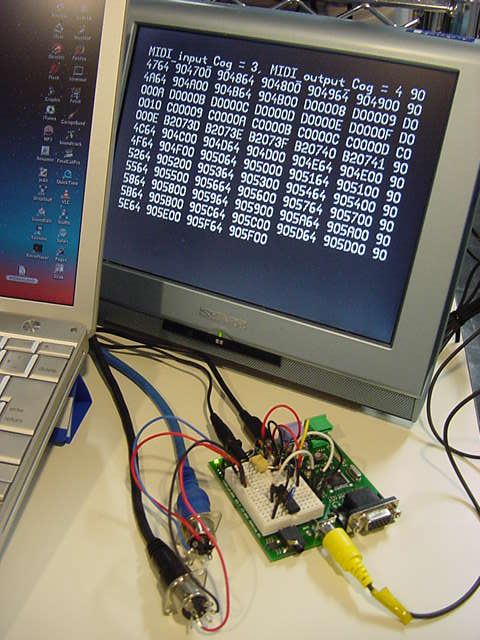
First of all, it is a call side of the main. The MIDI reception is first initialized, the Cog ID is displayed on the video output screen, the MIDI transmission is initialized next, and the Cog ID is displayed. Usual MIDI messages except real time and exclusive are received, it piles up in reception FIFO buffer of long that adds 0 in one head byte, and three bytes in the under are video output by the hexadecimal display. And, when this data is piled up again in transmission FIFO buffer of long, three bytes/two byte message of MIDI is transmitted here by the parallel processing.
{{ exp012.spin }}

CON
	_clkmode = xtal1 + pll16x
	_xinfreq = 5_000_000

OBJ
	Num : "Numbers"
	TV : "TV_Terminal"
	midiIn : "MidiIn03"
	midiOut : "MidiOut01"

PUB Main | dummy
	Num.Init
	TV.Start(12)

	TV.Str(string("MIDI_input_Cog ="))
	dummy := midiIn.start(7)
	TV.Str(Num.ToStr(dummy, Num#DEC))

	TV.Str(string(", MIDI_output_Cog ="))
	dummy := midiOut.start(6)
	TV.Str(Num.ToStr(dummy, Num#DEC))

	repeat
		dummy := midiIn.event
		if dummy <> -1
		midiOut.fifoset(dummy)
		TV.Str(Num.ToStr(dummy, Num#HEX7))
The following : continuously. It is the first of the complete, original MIDI transmission libraries. The subroutine call defends neatly and uses "Promise" here. FIFO of the MIDI transmission was packing of three bytes as the message, and here was seen as depth of 64longs.
VAR
	long tx_Head, tx_Tail, tx_Buff[64]

PUB start(_midiPin) : status
	midiPin := _midiPin
	tx_top := @tx_Head
	tx_end := @tx_Tail
	tx_fifo := @tx_Buff
	bitticks := clkfreq / 31_250
	longfill(@tx_Head,66,0)
	status := cognew(@asm_entry, 0)

PUB fifoset(_tx_data)
	tx_Buff[tx_Head] := _tx_data
	tx_Head := (tx_Head + 1) & $3F

DAT
                        org
asm_entry
                        mov     midiMask,#1
                        shl     midiMask,midiPin
                        or      dira,midiMask
:fifo_check
                        rdlong  t1,tx_end
                        rdlong  t2,tx_top
                        cmp     t1,t2                   wz
              if_z      jmp     #:fifo_check
                        mov     t2,t1
                        shl     t1,#2
                        add     t1,tx_fifo
                        rdlong  event_data,t1
                        mov     t1,t2
                        add     t1,#1
                        and     t1,#$3F
                        wrlong  t1,tx_end
                        mov     tx_data,event_data
                        shr     tx_data,#16
                        call    #send_event
                        and     tx_data,#%11100000
                        cmp     tx_data,#%11000000      wz
              if_z      jmp     #:byte_2
                        mov     tx_data,event_data
                        shr     tx_data,#8
                        call    #send_event
:byte_2
                        mov     tx_data,event_data
                        call    #send_event
                        jmp     #:fifo_check

send_event
                        xor     tx_data,#$FF
                        and     tx_data,#$FF
                        shl     tx_data,#1
                        or      tx_data,#1
                        mov     testBits,#10
                        mov     bitClk,cnt
                        add     bitClk,bitticks
:bit_send
                        shr     tx_data,#1              wc
                        muxc    outa,midiMask
                        waitcnt bitClk,bitticks
                        djnz    testBits,#:bit_send
send_event_ret          ret

t1                      long    0
t2                      long    0
midiMask                long    0
testBits                long    0
bitClk                  long    0
bitticks                long    0
midiPin                 long    0
tx_top                  long    0
tx_end                  long    0
tx_fifo                 long    0
tx_data                 long    0
event_data              long    0

                        fit
Even the hardware of the MIDI reception and the MIDI transmission is recorded on the breadboard construction of Propeller Demo Board, and the following are photographs of this "Expensive MIDI through box". It goes to the hexadecimal number display by the video signal with another Cog of Propeller, and any three Cog yet is not done. It is a quite happy chip when a variety of including it. Be it will A/D still, D/A, sensor I/F, and audio as follows, etc. I/O?
ˇˇ

ˇˇ


The part of "Liver" of this MIDI transmission assembler routine is the following when arranging and confirming it again. One byte data that transmits is put in tx_data, and CALL does the following routines.
send_event
                        xor     tx_data,#$FF
                        and     tx_data,#$FF
                        shl     tx_data,#1
                        or      tx_data,#1
                        mov     testBits,#10
                        mov     bitClk,cnt
                        add     bitClk,bitticks
:bit_send
                        shr     tx_data,#1              wc
                        muxc    outa,midiMask
                        waitcnt bitClk,bitticks
                        djnz    testBits,#:bit_send
send_event_ret          ret
Data is first reversed, the mask and AND are done, and "Stop bit" is secured because it reverses with hardware. Next, after the left shifts by one bit, "Start bit" is put. The width in bits of the MIDI rule is set here as a timer. This data is output by "shr tx_data,#1 wc", and it right shifts and it does, LSB of which Hami goes out is stored in the carry flag, and only the bit of the port in which it masks it corresponding to this carry flag (I/O pin for the MIDI transmission) is output by "muxc outa,midiMask" by one bit. It is a thing of setting the bit of each cereal by repeating this loop, and meeting with the timer.
UART (specialized hardware) has been used without fail about serial communications though a lot of MIDI processing microcomputer systems have been produced up to now. This is very the first time every one bit of the cereal is read with software, and it raises and lowers and the MIDI communication was achieved though 25 years have passed since it got acquainted with the microcomputer. Though it is Parallax Co. that gives priority to the IT education in the world such as MIT Propeller was exactly felt also that the taking a lesson from the past processor strongly.

Propeller Diary (3)