Propeller Diary (4)
Yoichi Nagashima
Propeller Diary (1)
Wednesday 26th, March 2008
Well, it is yesterday's continuation. Start method in VocalTract object The part of the following initialization was "Liver. " of the sound output exactly. It was a sloppy mistake by chance that had overlooked this by chance. Well, it is not a disadvantageous detour because it has considerably become accustomed to the assembler of Propeller by the favor either.ctrb_ := $18000000 + pos_pin & $3F ctrb_ += $04000000 + (neg_pin & $3F) << 9When < b>CRTB of the Propeller manual was seen, counter/timer relation in Cog of Propeller was written as follows and in detail. Because the audio output is a cereal, counter/timer is sure to be used absolutely.
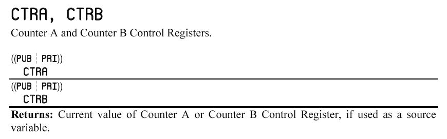
First of all, it is with ..spin explanation of CRTA/CRTB.. the above-mentioned, and arranges the following in a row how it is possible to apply it.
The format of the data set to CRTB by this program was the following. center>
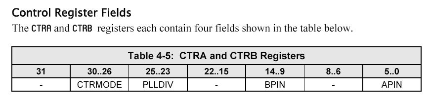
When it is confirmed to have initialized the data transmitted to CTRB by the initialization routine by the start method, it is the following.
ctrb_ := $18000000 + pos_pin & $3F ctrb_ += $04000000 + (neg_pin & $3F) << 9Then, if one most significant byte is said, it becomes < b>0001 1000+0000 0100=0001 1100. Because bit31 is disregard, CTRMODE of bit30..26 in five bits is < b>00111 Because the second byte is 0, PLLDIV of bit25.23 in three bits is < b>000 The meaning of each pin is the following.
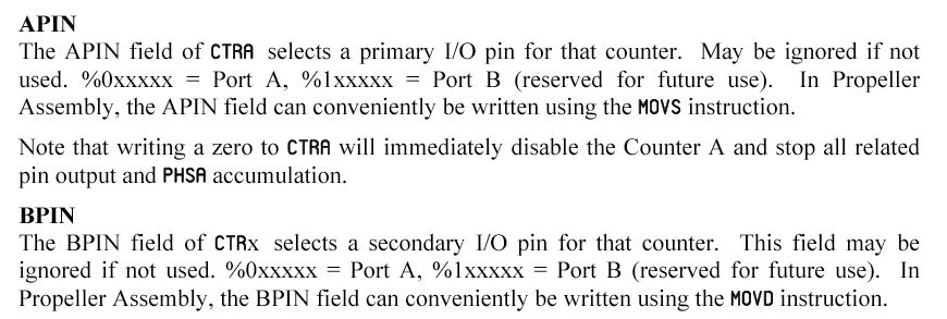
Therefore, because following PLLDIV is < b>000, "VCO / 128" will be output.
The explanation of CTRMODE is the following.

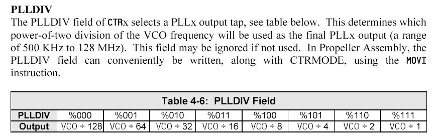
CTRMODE here was < b>00111, and it turned out that it was "DUTY differential" mode from the following tables. It seems only that it reverses logically according to this description though it is a stereo of two of pos and neg output. Then, when the signal of one of channels of the sound sounded with the stereo was upset (Exchanged it) and seen, it located to the center of the stereo with [bittari]. Though former sound had extended somehow like the stereo This was "Pseudostereo" "The monophonic signal was given and the reversing signal ..[hen] channel.. was given from an opposite channel" as it was exactly.
It finally became the following turns downloaded with Web here. this [Detekita] that understands counter of each Cogs of Propeller of strength ..necessity... The entire the block chart is the following.

When the explanation of this DUTY differential mode is seen because the reason for the complex one is that it is multi-purpose for a moment, it has been understood that it is good only in the following blocks.

Because this D/A output was expected to be going to be used variously in the future, the explanation of the manual decided to be arranged here neatly.
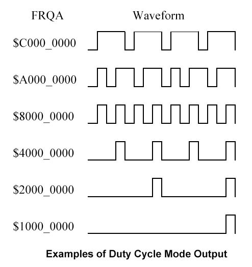
Duty Cycle modes of operationModes %00110 (DUTY single-ended) and %00111 (DUTY differential) on the surface appear similar to the NCO/PWM modes of operation; however the waveforms they produce are very different. The output of the Duty Cycle modes is the carry output of the PHSA register, whenever the PHSA register overflows (wraps around from $FFFF_FFFF to $0000_0000) the APIN is set to 1. The block diagram for this mode of operation is shown in Figure 9. If FRQA is $0000_0001, the carry bit of PHSA will be 1 only once every 2^32 (4,294,967,296) cycles. At an 80MHz system clock, this will occur approximately once every 54 seconds. Similarly if FRQA is $FFFF_FFFF, the carry bit of PHSA will be 0 only once every 2^32 cycles.
It is an output example as follows corresponding to the over explanation.
And, it used for D/A of the audio output as follows, and it explained the example.

It has come into view considerably by this ahead. Then, the following were first kept as a version that operated as well as VocalTrack.
And, first of all in the operation of the segment of the voice synthesis Because it had been understood to turn 13 kinds of parameters to the following segment and to interpolate it timewise, this part was cut. As a result, the program becomes only a numeric operation and the D/A output of 13 parameters though it is not a voice, it becomes, and a mere formant pedal point will come out.
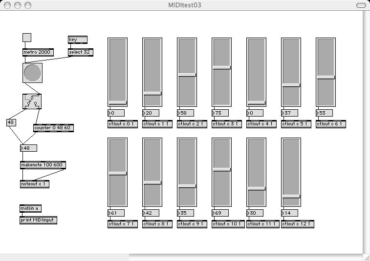
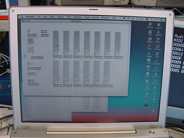
The Propeller software etc. that can be done making the setting of the parameter on the Max/MSP side on software, and corresponding are the following.
13 parameters of the voice synthesis were able to be changed into the pedal point by this in real time and individually. The part was refreshing as follows at the beginning.
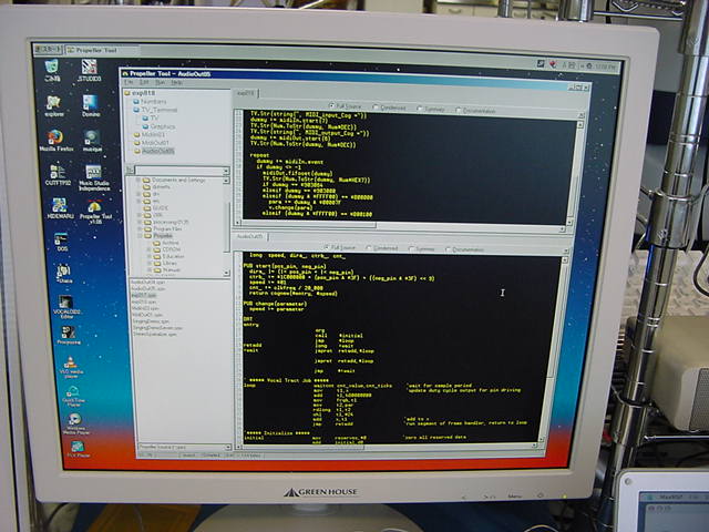
- exp017.spin
- AudioOut04.spin
- Max/MSP patchMIDItest03.mxt
VAR
	long  cog, tract, zzzz4, zzzz5, attenuation, zzzz6    '6 longs       ...must
	long  dira_, zzzz1, zzzz2, ctrb_, zzzz3, cnt_         '6 longs       ...be
	long  frames[4]                                       'many longs    ...contiguous

PUB start(parameters, pos_pin, neg_pin)
	dira_ |= (|< pos_pin + |< neg_pin)
	ctrb_ := $1C000000 + (pos_pin & $3F) + ((neg_pin & $3F) << 9)
	tract := parameters
	cnt_ := clkfreq / 20_000
	return cog := cognew(@entry, @attenuation)

PUB change
	bytemove(@frames[0] + 3, tract, 13)

DAT
entry
                        org
                        call    #initial
                        jmp     #loop
retadd                  long    :wait
:wait                   jmpret  retadd,#loop
                        mov     f_ptr,par
                        add     f_ptr,#4*8+3
                        movd    :set2,#par_curr
                        mov     f_cnt,#13
:set                    jmpret  retadd,#loop
                        rdbyte  t1,f_ptr
                        shl     t1,#24
:set2                   mov     par_curr,t1
                        add     :set2,d0
                        add     f_ptr,#1
                        djnz    f_cnt,#:set
                        jmp     #:wait

' ##### Vocal Tract Job #####
loop                    waitcnt cnt_value,cnt_ticks     'wait for sample period
                        rdlong  t1,par                  'perform master attenuation
                        sar     x,t1
                        mov     t1,x                    'update duty cycle output for pin driving
                        add     t1,h80000000
                        mov     frqb,t1
                        mov     t1,par                  'update sample receiver in main memory
                        add     t1,#1*4
                        wrlong  x,t1
:White_noise_source     test    lfsr,lfsr_taps  wc      'iterate lfsr three times
                        rcl     lfsr,#1
------
                        jmp     retadd                  'run segment of frame handler, return to loop
From the parents object on the call side The method of calling when either of 13 kinds of parameters was changed was assumed to be change. 13 parameters are always transmitted from the area of Propeller sharing RAM in Cog on corresponding to this, and everything is put on the variable for the internal arithmetic as the left shifting by 24 bits. Here is processing of the segment interpolation and a complex point before.
Moreover, at the beginning. The part in the focus it where the following parts following weight corresponding to the sampling clock wrote changeable Duty data in the counter became clear. One FRQB was here though it was not found easily.
As for this part, variable "x" is succeeded from the last processing as PWM data written in the counter.rdlong t1,par 'perform master attenuation sar x,t1 mov t1,x 'update duty cycle output for pin driving add t1,h80000000 mov frqb,t1 mov t1,par 'update sample receiver in main memory add t1,#1*4 wrlong x,t1
Volume control (Data is shifted and reduced) parameter is stored in t1 in an upper loading part, and first of all, a right shift does and reduces data only to the t1 bit with the signature bit of MSB left. This is returned to t1 again. However, because the concept named [attene-shon] had already been omitted, the first two lines became unnecessary, and were cut among these three lines.rdlong t1,par 'perform master attenuation sar x,t1 mov t1,x 'update duty cycle output for pin driving
And, the upper part and $80000000 is added to t1 though only here actually remains. This is just "Reverse of the signature bit. " Because the time that reverses digitally becomes a sampling value as for PWM Thus, the sign might be reversed every sampling period, and an analog value be obtained as width of time from it. And, because it was a value to return it from the method of parents to the inquiry of "Present sample point", this was omitted as follows.mov t1,x 'update duty cycle output for pin driving add t1,h80000000 mov frqb,t1
Thus, it has become it only as follows the part of this essential D/A output is losing momentum for a moment.mov t1,par 'update sample receiver in main memory add t1,#1*4 wrlong x,t1' ##### Vocal Tract Job ##### loop waitcnt cnt_value,cnt_ticks 'wait for sample period mov t1,x 'update duty cycle output for pin driving add t1,h80000000 mov frqb,t1 :White_noise_source test lfsr,lfsr_taps wc 'iterate lfsr three times rcl lfsr,#1 ------ jmp retadd 'run segment of frame handler, return to loopNot finally deciphering it by this program in this became only a numeric operation of the voice synthesis algorithm and the part of CORDIC. However, this can be confirmed at any time if it needs it only it is to describe the theory as it is maybe. It is a part of the output of "Digital audio in Propeller" and the sound that wanted to know here. Then, only the processing every sampling period is left. The target decided to be corrected as a complete original like the program that output the sound by the same mechanism.
Thursday 27th, March 2008
It decided to experiment on the sound output by "DUTY differential mode" that existed in the Propeller manual. It is scheduled to make it to the minimum the part of Propeller.An opening part is the same as the situation to date as follows quite.
{{ exp018.spin }}
CON
	_clkmode = xtal1 + pll16x
	_xinfreq = 5_000_000

OBJ
	Num : "Numbers"
	TV : "TV_Terminal"
	midiIn : "MidiIn03"
	midiOut : "MidiOut01"
	v : "AudioOut05"
And, the part of the main : as follows. Only one data of seven bits was sent from MIDI to Propeller for the time being.
PUB Main | dummy, para
	Num.Init
	TV.Start(12)

	TV.Str(string("Audio_output_Cog ="))
	dummy := v.start(10, 11)
	TV.Str(Num.ToStr(dummy, Num#DEC))
	TV.Str(string(", MIDI_input_Cog ="))
	dummy := midiIn.start(7)
	TV.Str(Num.ToStr(dummy, Num#DEC))
	TV.Str(string(", MIDI_output_Cog ="))
	dummy := midiOut.start(6)

	TV.Str(Num.ToStr(dummy, Num#DEC))
	repeat
		dummy := midiIn.event
		if dummy <> -1
			midiOut.fifoset(dummy)
			TV.Str(Num.ToStr(dummy, Num#HEX7))
			if dummy == $903064
			elseif dummy == $903000
			elseif (dummy & $FFFF00) == $B00000
				para := dummy & $00007F
				v.change(para)
			elseif (dummy & $FFFF00) == $B00100
AudioOut05.spin The part of opening spin was made easy as follows. An initial value of the total value was seen for the time being as $01.
VAR
	long  speed, dira_, ctrb_, cnt_

PUB start(pos_pin, neg_pin)
	dira_ |= (|< pos_pin + |< neg_pin)
	ctrb_ := $1C000000 + (pos_pin & $3F) + ((neg_pin & $3F) << 9)
	speed := $01
	cnt_ := clkfreq / 20_000
	return cognew(@entry, @speed)

PUB change(parameter)
	speed := parameter
The parameter : the one sent from the parents object. It receives by the change method, and this is stored in internal variable speed. And, the assembler area is all as follows.
DAT
entry
                        org
                        call    #initial
                        jmp     #loop
retadd                  long    :wait
:wait                   jmpret  retadd,#loop
                        jmp     #:wait

loop                    waitcnt cnt_value,cnt_ticks
                        mov     t1,x
                        add     t1,h80000000
                        mov     frqb,t1
                        mov     t2,par
                        rdlong  t1,t2
                        shl     t1,#24
                        add     x,t1
                        jmp     retadd

initial                 mov     reserves,#0
                        add     initial,d0
                        djnz    clear_cnt,#initial
                        mov     t1,par
                        add     t1,#4
                        rdlong  dira,t1
                        add     t1,#4
                        rdlong  ctrb,t1
                        add     t1,#4
                        rdlong  cnt_ticks,t1
                        mov     cnt_value,cnt
                        add     cnt_value,cnt_ticks
initial_ret             ret

h80000000               long    $80000000
d0                      	long    $00000200
clear_cnt               long    $1F0 - reserves
reserves
cnt_ticks               res     1
cnt_value               res     1
x                       res     1
t1                      res     1
t2                      res     1
The sound of a familiar "Saw-tooth wave" in the synthesizer rang when compiling this program with the Propeller tool and downloading and executing it. The pitch changes greatly when the parameter is changed from MIDI. In this, it stood in the starting point of a temporary audio output.
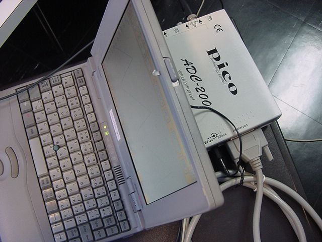
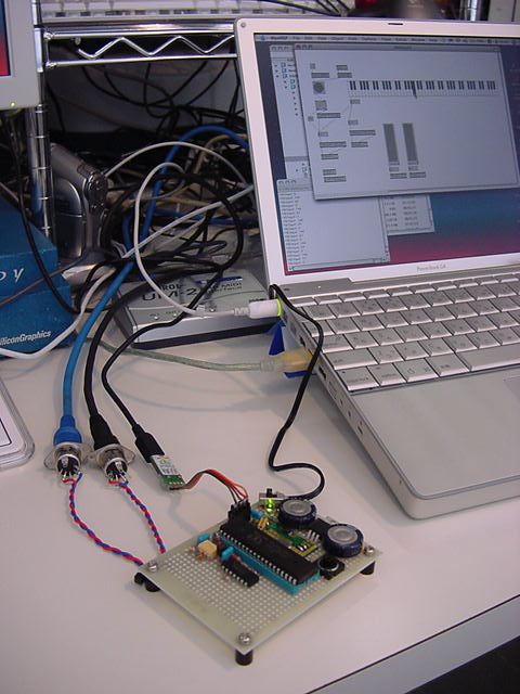
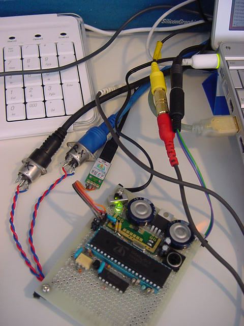
The note of Windows 95 decided to be excavated to see the shape of waves because it is special for the first time in years, to tie [oshiro] bought by the moon electron in autumn, and to see this analog output wave type. The battery was able to forward the screen shot of the oscilloscope to the server by safely moving in longevity though re-reset was necessary. The shape of waves is the following.
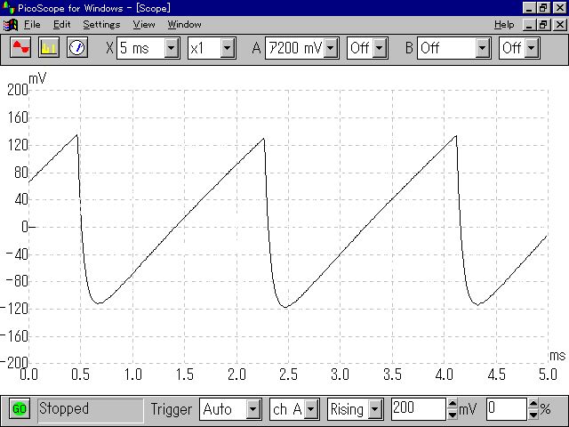
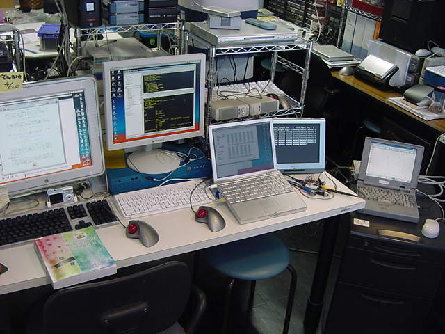
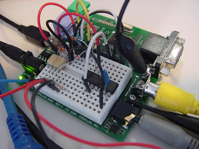
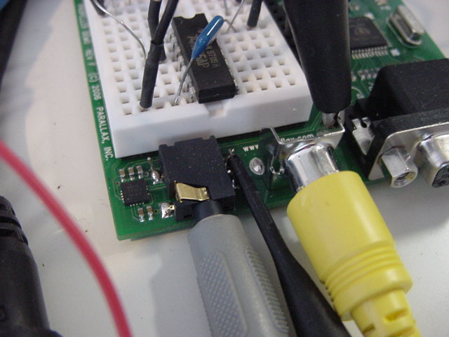
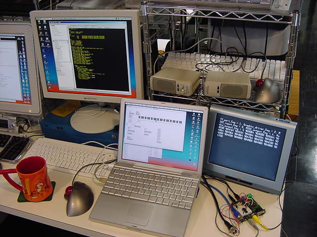
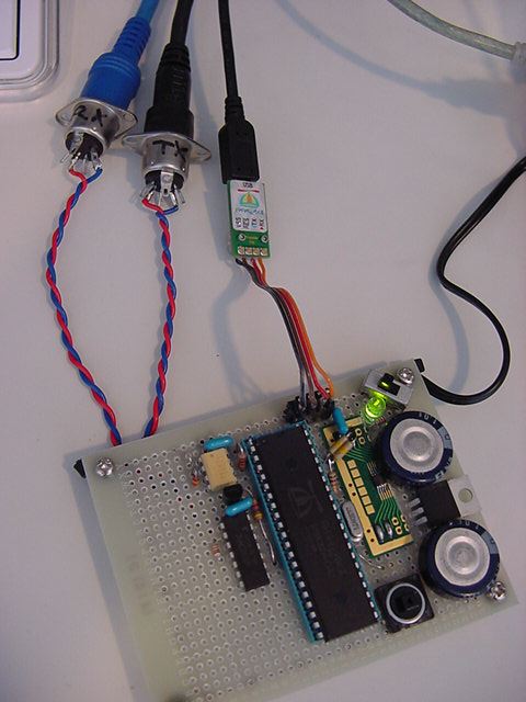
It seems to go out neatly with p-p by about 2.5V because the probe adjusts the voltage to 1/10. The signal to which the polarity reversed of course had come out from the other channel. It is an appearance of this experiment as follows. A small board of Propeller is scenery enclosed by four personal computers.


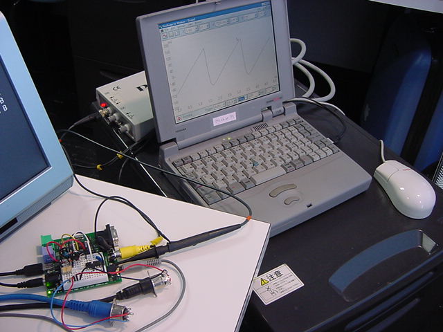

Because the value from $00000000 to $FFFFFFFF that totals the parameter simply every sampling period is written in FRQB as for the shape of waves seen here, it becomes such a saw-tooth wave. Because the signature table is stored in internal ROM of Propeller The following target decided to change the pitch, to change the volume in addition, and to audio output the signature wave.
It refers the processing of attenuation in VocalTract.spin, and as for the volume, it first of all is 0 times, 1/2 times, and 1/4 times. ---It made it to the thing assumed a simple shift of seven bits (Up to 1/128 times). A pertinent part of the main of sending as follows The value of 0-7 was sent to Propeller by the following number of the control change.
  repeat
    dummy := midiIn.event
    if dummy <> -1
      midiOut.fifoset(dummy)
      TV.Str(Num.ToStr(dummy, Num#HEX7))
      if dummy == $903064
      elseif dummy == $903000
      elseif (dummy & $FFFF00) == $B00000
        para := dummy & $00007F
        v.change1(para)
      elseif (dummy & $FFFF00) == $B00100
        para := dummy & $000007
        v.change2(para)
Receiving newly established variable volume, and did as follows.
VAR
	long  speed, dira_, ctrb_, cnt_, volume

PUB start(pos_pin, neg_pin)
	dira_ |= (|< pos_pin + |< neg_pin)
	ctrb_ := $1C000000 + (pos_pin & $3F) + ((neg_pin & $3F) << 9)
	speed := $01
	volume := 0
	cnt_ := clkfreq / 44_100
	return cognew(@entry, @speed)

PUB change1(parameter)
	speed := parameter

PUB change2(parameter)
	volume := parameter & %0111

DAT
entry
                        org
                        call    #initial
                        jmp     #loop
retadd                  long    :wait
:wait                   jmpret  retadd,#loop
                        jmp     #:wait

loop                    waitcnt cnt_value,cnt_ticks

                        mov     y,x
                        mov     t1,par
                        add     t1,#4*4
                        rdlong  t2,t1
                        and     t2,#%0111
                        sar     x,t2
                        add     x,h80000000
                        mov     frqb,x
                        mov     x,y
                        mov     t2,par
                        rdlong  t1,t2
                        shl     t1,#24
                        add     x,t1
                        jmp     retadd
Total value x was stored in y once, and only the passed number of bits did a right shift by < b>SAR instruction only in the place where D/A was output. Because this instruction was different from the SHR instruction, and the sign bit of MSB was left just as it is, the part of [attene-ta] was able to be achieved only by this easily.
Because the signature table of Propeller is naturally stored only at 1/4 cycles, it is necessary to adjust reading and the polarity according to the phase. By the way, this part decided to be mimicked as the table in Propeller was referred to in the part of "sine" as follows, and the phase and the polarity were adjusted very much in VocalTract.spin.
sine              	shr     t2,#32-13               	'get 13-bit angle
                        test    t2,h00001000    wz      	'get sine quadrant 3|4 into nz
                        test    t2,h00000800    wc      	'get sine quadrant 2|4 into c
                        negc    t2,t2                   		'if sine quadrant 2|4, negate table offset
                        or      t2,h00007000            	'insert sine table base address >> 1
                        shl     t2,#1                   		'shift left to get final word address
                        rdword  t2,t2                   		'read sine word from table
                        negnz   t2,t2                   		'if quadrant 3|4, negate word
                        shl     t2,#15                  		'msb-justify result
The signature table in the main memory is 2049, that is, the width of 16 bits in following according to the Propeller manual "Word. " The address is $E000-$F001. The fraction goes out with even the maximum value of the terminal at 1/4 cycles of the first 0 values because they are 1/4 cycles.

In the routine above, phase t2 is full-scale 13 bits.
sine shr t2,#32-13 'get 13-bit anglePhase total value t2 is put in a full scale in 13 bits on.
test t2,h00001000 wz 'get sine quadrant 3|4 into nzThe MSB is seen by the above-mentioned, and if it is a cycle (3/4 quarter) of the latter half, Z flag is hoisted.
test t2,h00000800 wc 'get sine quadrant 2|4 into cIf they are 2/4 quarter, C flag is hoisted by the above-mentioned.
negc t2,t2 'if sine quadrant 2|4, negate table offsetIt reads it by the opposite phase in reversing t2 by the above-mentioned by this carry.
                        or      t2,h00007000            	'insert sine table base address >> 1
                        shl     t2,#1                   		'shift left to get final word address
                        rdword  t2,t2                   		'read sine word from table
It is adjusted by the above-mentioned to the offset of the address of the table. The address is read because data is one word and after it does of twice, an actual signature table value is read to t2.
                        negnz   t2,t2                   		'if quadrant 3|4, negate word
                        shl     t2,#15                  		'msb-justify result
The polarity is reversed by the above-mentioned with z flag at the end, and the result has been returned to the long length of 32 bits.
A program the following of built this part into the program of independence, experimented for a while, and gave the sign for the time being was able to be done.
The shape of waves became a beautiful signature wave as follows.

44.1 It is easy following work that processes every sampling period changed to KHz.
It is a part that corresponds while programming it as follows.
- Sampling value x is kept in y.
- It ..output x.. drops in the [attene-ta] value.
- PWM audio is output by writing x in FRQB.
- Phase total value phase of a wavy reading is totaled.
- The signature table is read by this.
- Kept sampling value y is returned to x.
- The value of the signature is added to x.
loop                    waitcnt cnt_value,cnt_ticks
                        mov     y,x
                        mov     t1,par
                        add     t1,#4*4
                        rdlong  t2,t1
                        and     t2,#%0111
                        sar     x,t2
                        add     x,h80000000
                        mov     frqb,x
                        mov     t1,par
                        rdlong  t2,t1
                        add     phase,t2
                        mov     t2,phase
                        shr     t2,#32-13               'get 13-bit angle
                        test    t2,h00001000    wz      'get sine quadrant 3|4 into nz
                        test    t2,h00000800    wc      'get sine quadrant 2|4 into c
                        negc    t2,t2                   'if sine quadrant 2|4, negate table offset
                        or      t2,h00007000            'insert sine table base address >> 1
                        shl     t2,#1                   'shift left to get final word address
                        rdword  t1,t2                   'read sine word from table
                        negnz   t1,t1                   'if quadrant 3|4, negate word
                        shl     t1,#7
                        mov     x,y
                        add     x,t1
                        jmp     retadd
It is not the one that can still be called "Oscillator" though "Signature" went out for the time being by this. Actually, because there is RC filter in the pin output of Propeller As the frequency response, considerable LPF hangs, and the level of each frequency changes considerably. This adds the improvement that assumes it is reluctant, and becomes an oscillator a little more.
Friday 28th, March 2008
The periodical waveform is generable any signal if a wavy table is referred for occurring of the signature wave. Let's adjusted sampling to same 44.1KHz as CD, and arrange the part of a wavy pitch neatly here.When the system was similarly evolved from the signal generation to MIDI musical instruments with AKI-H8 before, it had the data table of each pitch for MIDI based on 12 capitation average rate in ROM of AKI-H8. However, because sharing ROM and RAM in Cog have in capacity in Propeller, too the strategy that uselessly secures such abundant data tables cannot be adopted.
On the other hand, the processing performance of Cog of clock 80MHz considerably :. Hurry must be in time for time traffic of performance information on same MIDI somehow or other in software perhaps. It has the phase total value for one octave from experienced intuition here as a table. Cog of the Top object decided to process the pitch in real time corresponding to the number of MIDI notes. Let's first examine data as a design on the desk, and verify whether the sound rings really by the pitch.
The time of the access of the shape of waves hangs by the twice if the data of the phase total value becomes half, and the octave falls on the pitch of the generated sound. Then, a right bit shift only has to do data only by the octave when it is lower than it if there is 12 phase total value data for one octave of the highest compass. This will not be adopted because the operation of highly accurate multiplication and division of "2 of the 12th power roots" is necessary to generate 12 sounds of the average rate from one data, and it have 12 pieces foolishly. It is in MIDI as follows.
-------------------------------------------------------
Octave||                     Note Numbers
   #  || C   | C#  | D   | D#  | E   | F   | F#  | G   | G#  | A   | A#  | B
-------------------------------------------------------
   0  ||   0 |   1 |   2 |   3 |   4 |   5 |   6 |   7 |   8 |   9 |  10 |  11
   1  ||  12 |  13 |  14 |  15 |  16 |  17 |  18 |  19 |  20 |  21 |  22 |  23
   2  ||  24 |  25 |  26 |  27 |  28 |  29 |  30 |  31 |  32 |  33 |  34 |  35
   3  ||  36 |  37 |  38 |  39 |  40 |  41 |  42 |  43 |  44 |  45 |  46 |  47
   4  ||  48 |  49 |  50 |  51 |  52 |  53 |  54 |  55 |  56 |  57 |  58 |  59
   5  ||  60 |  61 |  62 |  63 |  64 |  65 |  66 |  67 |  68 |  69 |  70 |  71
   6  ||  72 |  73 |  74 |  75 |  76 |  77 |  78 |  79 |  80 |  81 |  82 |  83
   7  ||  84 |  85 |  86 |  87 |  88 |  89 |  90 |  91 |  92 |  93 |  94 |  95
   8  ||  96 |  97 |  98 |  99 | 100 | 101 | 102 | 103 | 104 | 105 | 106 | 107
   9  || 108 | 109 | 110 | 111 | 112 | 113 | 114 | 115 | 116 | 117 | 118 | 119
  10  || 120 | 121 | 122 | 123 | 124 | 125 | 126 | 127 |
-------------------------------------------------------
In the highest compass of the number of MIDI notes, It only has to have everything from "Note 116 = G#9" to "Note 127 = G10". Only whole tone formally extends Note up to 129 up, and, first, "Note 129 = A10" is calculated though it doesn't exist here by the standard of the pitch will being to use "A4 = 440Hz" in the MIDI rule for easiness. This is 6 octaves of A4 because it is height, and exactly 440 * 64 = It is 28160Hz.
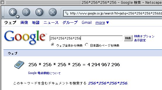
The sampling frequency is 44.1KHz, and time of the one cycle is about 22675.736 microseconds. The cycle of 28.160KHz of A10 is about 35511.363 microseconds. Because the data of the total value is fractions below decimal point, it is theoretically computable though the pitch of A10 has exceeded 22.05KHz of the sampling theorem. It becomes the following from the proportion because it becomes 28.160KHz if data x is totaled by the same sampling while becoming 44.1KHz if 32 bit full (1 long) ,in a word, $100000000 is totaled if the total value data for obtained A10 is assumed to be x.
$100000000 : 44.1 = x : 28.160 The integral value of "x = 2742546010" was obtained by calculating the following Google calculators.
If "2 of the 12th power roots" is similarly calculated as y with the Google calculator based on this numerical value, it becomes it as follows.
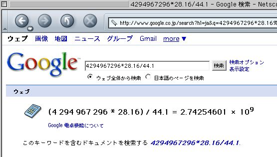
y = 2^(1 / 12) = 1.05946309 Therefore, "x / y / y" was calculated with the Google calculator similarly for G10 of MIDI highest sound, and it became it as follows.
G10 : (2742546010 / 1.05946309) / 1.05946309 = 2443330740 It calculated similarly with the Google calculator, and the following were obtained because it became data ..under the semitone.. if it went out of here and it divided by y further the result of coming.
F#10 : 2443330740 / 1.05946309 = 2306197130
F10 : 2306197130 / 1.05946309 = 2176760240
E10 : 2176760240 / 1.05946309 = 2054588080
Eb10 : 2054588080 / 1.05946309 = 1939272920
D10 : 1939272920 / 1.05946309 = 1830429900
C#10 : 1830429900 / 1.05946309 = 1727695770
C10 : 1727695770 / 1.05946309 = 1630727660
B9 : 1630727660 / 1.05946309 = 1539201960
Bb9 : 1539201960 / 1.05946309 = 1452813200
A9 : 1452813200 / 1.05946309 = 1371273070
Ab9 : 1371273070 / 1.05946309 = 1294309430
By the way, the last data was divided by y further for the confirmation and two was multiplied.
(G9) : 1294309430 / 1.05946309 * 2 = 2434330860 This is 2443330740 of G10 or is near, and the accumulation of the error margin is an order that not worried. Having this data on the side intended for parents as a constant data, shifting the octave corresponding to the number of MIDI notes, and having passed it to AudioOut06.spin that has not been changed at all as speed parameter are the following programs.
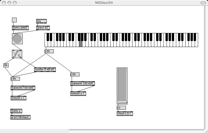
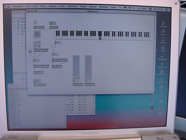
{{ exp020.spin }}

CON
	_clkmode = xtal1 + pll16x
	_xinfreq = 5_000_000

DAT
  f_number	long      1294309430,1371273070,1452813200,1539201960
              		long      1630727660,1727695770,1830429900,1939272920
              		long      2054588080,2176760240,2306197130,2443330740

OBJ
	Num : "Numbers"
	TV : "TV_Terminal"
	midiIn : "MidiIn03"
	midiOut : "MidiOut01"
	v : "AudioOut06"

PUB Main | dummy, para, p1
	Num.Init
	TV.Start(12)

	TV.Str(string("Audio_output_Cog ="))
	dummy := v.start(10, 11)
	TV.Str(Num.ToStr(dummy, Num#DEC))
	TV.Str(string(", MIDI_input_Cog ="))
	dummy := midiIn.start(7)
	TV.Str(Num.ToStr(dummy, Num#DEC))
	TV.Str(string(", MIDI_output_Cog ="))
	dummy := midiOut.start(6)
	TV.Str(Num.ToStr(dummy, Num#DEC))

	repeat
		dummy := midiIn.event
		if dummy <> -1
			midiOut.fifoset(dummy)
			TV.Str(Num.ToStr(dummy, Num#HEX7))
			if (dummy & $FF00FF) == $900064
				v.change2(0)
				p1 := (dummy & $007F00) >> 8
				para := f_number[ (p1+4) // 12 ] >> ( (127-p1) / 12 )
				v.change1(para)
			elseif (dummy & $FF00FF) == $900000
				v.change2(7)
			elseif (dummy & $FFFF00) == $B00000
				para := dummy & $000007
				v.change2(para)
This program Max/MSP patch made as follows [Ni], the unison was able to be confirmed because of a piano sound of [sofutoshinse] on the Mac side and the generation sound of Propeller. It is the easy one only to muffle.
It is at the following in the program for a moment that it is tricky.
para := f_number[ (p1+4) // 12 ] >> ( (127-p1) / 12 ) Remainder operator "//" was handled to the part of the index of the octave and 12 arranged arrays because it repeated every 12 pieces. Here is little notes because it uses it in Propeller for the binary numerical value though "%" is usually used. Only a lot of right shifts are done by the octave low, and usual division "/" (Throw it away too much) is used here.
In this, to the Propeller board where this program runs The application of the electric piano's etc. tying with MIDI, and using it by the standalone as easy musical instruments became considerably familiar. Now, there is will being not to go deep into a district here too much with Propeller and it will change the halberd ahead.
2008年3月30日(日)
Propellerで目指すところに関係して、 このページ を改訂した。 これまでのインスタレーションは、基本的にというシステム構成をしていた。 AKI-H8で作ったインターフェース、I-Cubeなど、 そしてGAINERも、この第2/第4項目のインターフェースである。 Propellerについても、ここまでの実験で、この領域に十分に参加できる可能性は確信した。
- 外界からの入力を検出するセンサ
- センサからホストへのインターフェース
- ホストPC(Max/MSP/jitter, Flash, Processing等)
- ホストから(広義)ディスプレイへのインターフェース
- 外界に反応を返す(広義の)ディスプレイ
しかしさらに、もしインターフェースの部分の情報処理能力が高いのであれば、 第3項目まで含めて、つまりパソコンを不要としてシステムを構成できる。 Propellerには、この可能性を強く感じる。 このページ のインスタレーションの中にはごく少数、その発想でAKI-H8だけで実現したものもあるが、 まだまだホストPCは全盛である。 とりあえずAKI-H8やGAINERやBasicStampやPICに加わることから始めるとして、 目標はそこで終わらず、より高いところを目指したい。
さて、明日から2日間は学科会議合宿でPropellerと遊ぶことも出来ないので、 今日はちょっとだけの改造をすることにした。 これまで作ってきたPropellerソフトウェアでは、 ビデオ出力の部分は、Parallax社の提供したオブジェクトをそのまま、 ソフトウェア部品として利用してきた。 しかし、せっかくなら不要な部分を削ったり、機能を追加してオリジナル化してみたい。 そこで、OBJモジュールで参照されている
について、コピーしてオリジナル名としたものをカレントディレクトリに置いて、 実験することにした。後ろの2つは、「TV_Terminal.spin」から参照されているものである。
- Numbers.spin
- TV_Terminal.spin
- TV.spin
- Graphics.spin
親オブジェクトの方は、exp020.spinをコピーしてexp021.spinとリネームし、 まずは「MIDIを受けてサイン波形を生成する」というSPECは変更せず、 子オブジェクト・孫オブジェクトの改訂だけを行うことにした。 対象となるのは、
である。 まずは、簡単に完結していそうな「E_Numbers01.spin」を調べた。
- E_Numbers01.spin
- E_TV_Terminal01.spin
- E_TV01.spin
- E_Graphics01.spin
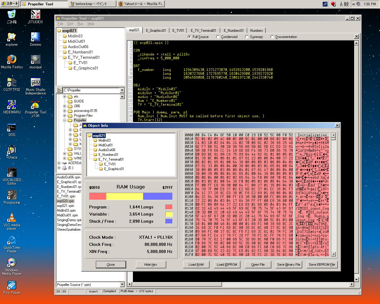
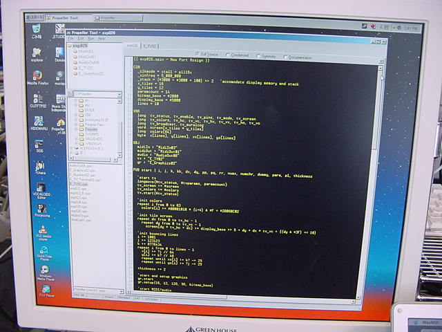
最初に、各オブジェクトのソースをリネームしただけの全プログラムをコンパイルして、 「Object Info」によって、以下のメモリ使用量のスクリーンショットを撮った。 不要な機能を削減したとして、どのくらい「効く」のかをテストするためである。

「E_Numbers01.spin」は、テキスト/ストリングの処理メソッドをごっそり集めたオブジェクトである。 しかし、基本的にビデオ出力のデバッグ画面に、10進あるいは16進でデータを表示する以外の機能については、 それほど使う予定もないので、カットすることにした。 削除したメソッドは以下の2つである。
さらに、使用しないモードの表示フォーマット用データをばっさりと切ってみたが、 以下のように、プログラムが56longs減っただけで、ほとんど影響が無かった。
- PUB FromStr(StrAddr, Format): Num | Idx, N, Val, Char, Base, GChar, IChar, Field
- PRI InBaseRange(Char, Base): Value
続いて、親オブジェクトから呼ばれているもう一つの「TV_Terminal.spin」を調べた。 この中には、テキスト表示のメソッドと、10進、16進、バイナリ、の3種類で数値を表示するメソッドがあったが、 数値表示はE_Numbers01.spinのNum.ToStrメソッドを使ってテキスト表示しているので、 数値表示の部分をカットすることにした。 削除したメソッドは、ビデオ表示のstopを入れて以下の4つである。
しかし以下のように、プログラムが37longs減っただけで、ほとんど影響が無かった。
- PUB stop
- PUB dec(value) | i
- PUB hex(value, digits)
- PUB bin(value, digits)
RAMに広大なグラフィックメモリを確保しているのもここであるが、 とりあえずまずはここは手を付けていない。

続いて、「E_TV01.spin」を調べた。 トップオブジェクトの初期化では、MIDIの入出力と、オーディオについては、 初期化の際にCog番号が返ってきて、それをビデオ表示した。 ところが、ビデオだけは「TV_Terminal.spin」の中で単に「TV.Start」を呼ぶだけで、 何も戻ってこなかった。 これは、そのさらに下の(子の子で孫メソッド)、「E_TV01.spin」の中のstartメソッドを呼んでいたからである。 そこで、この孫メソッドからの返り値としてCog番号を受け取り、 さらに子メソッドとして返すようにして、トップで無事に全ての初期化のCog番号が表示された。
「E_TV01.spin」は機能として、ビデオ出力の「NTSC」「PAL」の両方に対応している。 まずPALを使うことはないのでここをカットしようとしたが、 かなりトリッキーに両方に対応したコードとなっていたので、これは断念した。 Propellerの設計思想として、「NTSC用」「PAL用」などと冗長に両方のプログラムを用意して、 ビデオモードに対応してそのいずれかにジャンプする、などというのはダサイのだろう。 まだまだ、プログラムROMが潤沢にある旧来型のマイコンの発想だったことを反省した。
続いて、「E_Graphics01.spin」を調べた。 これは凄いオブジェクトであり、専用に1つのCogを使って、グラフィックドライバを構成していた。 「TV_Terminal.spin」からは、上記のtv.startと、こちらのためのgr.startの2つのNEWCOGを発令していた。 そこで、この両方から起動Cog番号を返して、 TV_Terminal.spinでは片方を10倍して返して、トップオブジェクトでデコードして、両方を表示するようにした。 カットしたのはstopメソッドぐらいなので、以下のようにちょっとサイズが増えた。
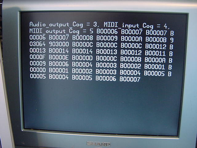
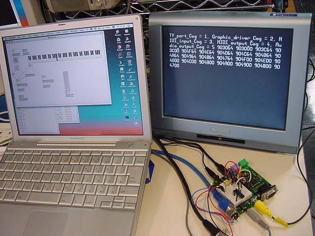
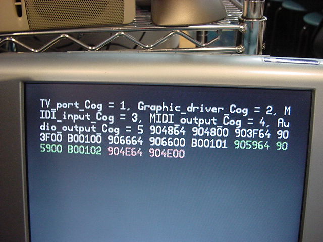
ここまでで、システムを構成しているPropellerソースは以下の8本である。 Cog IDやMIDI入力の情報をリアルタイムにビデオ出力し、 MIDIを送受信し、そのMIDIノートナンバに対応したピッチのサイン波形をオーディオ出力する、 という仕事を、6個のCogsによって実行している。 時分割でも割り込みでもなく各Cogsは自分の仕事を並列処理するシステムである。

これによって、以下のように、ビデオモニタからは、メイン(Cog ID=0)以外の、 全てのCogsの番号が表示されるようにできた。
- メイン exp021.spin
- サウンド出力 AudioOut06.spin
- MIDI入力 MidiIn03.spin
- MIDI出力 MidiOut01.spin
- 数値データ変換 E_Numbers01.spin
- ビデオターミナル出力 E_TV_Terminal01.spin
- ビデオ出力 E_TV01.spin
- グラフィックドライバ E_Graphics01.spin

グラフィックドライバ・オブジェクトの「E_Graphics01.spin」を眺めてみると、 かなり強力なグラフィックメソッドを完備していることが判明した。 これは、ビデオ・インスタレーションにはもってこいである。 ただし現状では、これはトップから見て孫メソッドなので、いちいち「TV_Terminal.spin」を介して制御する必要がある。 初期設定のCog番号を返す方法も、これが原因でちょっとダサいものになっている。 そこで、「E_TV01.spin」と「E_Graphics01.spin」を、 「TV_Terminal.spin」と同じ階層に並べられないか、実験してみた。 これが可能となれば、トップオブジェクトから直接に、グラフィックドライバのメソッドを利用できる筈である。
そして、メインとグラフィクス関係の3つ、の計4本のソースをコピーしてリネームし、 同じ動作を行うかチェックしながら改造した結果、結論として「出来ない」ことが判明した。 具体的には、まず親オブジェクト「exp022.spin」の該当部分は以下である。
{{ exp022.spin }}

------

OBJ
	midiIn : "MidiIn03"
	midiOut : "MidiOut01"
	audio : "AudioOut06"
	Num : "E_Numbers02"
	TV : "E_TV_Terminal02"
	gr : "E_Graphics02"

PUB Main | dummy, para, p1
	Num.Init                      { Num.Init MUST be called before first object use. }
	para := TV.Start1(12)
	dummy := TV.Start2
	TV.out(0)                     { display home }
	TV.Str(string("TV_port_Cog ="))
	TV.Str(Num.ToStr(para, Num#DEC))
	TV.Str(string(", Graphic_driver_Cog ="))
	TV.Str(Num.ToStr(dummy, Num#DEC))
------

	repeat
		dummy := midiIn.event
		if dummy <> -1
			midiOut.fifoset(dummy)
			TV.Str(Num.ToStr(dummy, Num#HEX7))
		if (dummy & $FF00FF) == $900064
------
		elseif (dummy & $FFFF00) == $B00100
			para := dummy & $000003
			TV.gr_test(para)
'			gr.color(para+1)
ここで、子オブジェクト「E_TV_Terminal01.spin」の該当部分は以下である。
OBJ
	tv    : "E_TV02"
	gr    : "E_Graphics02"

PUB gr_test(para)
	gr.color(para+1)

PUB start1(basepin) : status
''  basepin = first of three pins on a 4-pin boundary (0, 4, 8...) to have
''  1.1k, 560, and 270 ohm resistors connected and summed to form the 1V,
''  75 ohm DAC for baseband video
	bitmap_base := (@bitmap + $3F) & $7FC0
	repeat x from 0 to x_tiles - 1
		repeat y from 0 to y_tiles - 1
			screen[y * x_tiles + x] := bitmap_base >> 6 + y + x * y_tiles
	tvparams_pins := (basepin & $38) << 1 | (basepin & 4 == 4) & %0101
	longmove(@tv_status, @tvparams, paramcount)
	tv_screen := @screen
	tv_colors := @color_schemes
	status := tv.start(@tv_status)

PUB start2 : status
	status := gr.start
	gr.setup(x_tiles, y_tiles, 0, y_screen, bitmap_base)
	gr.textmode(x_scale, y_scale, x_spacing, 0)
	gr.width(width)
また、孫オブジェクト「E_Graphics02.spin」の該当部分は以下である。
親オブジェクトの「exp022.spin」では、OBJブロックで、子オブジェクトだけでなく、 孫オブジェクトも(強制的に)定義している。 そして、このプログラムを実行すると、MIDIコントロールチェンジ0番のデータとして、 子メソッド「TV.gr_test(para)」にパラメータpara(0-3) が渡される。 これは孫メソッド「color(c)」にパラメータcとして渡されるので、 システムとしての動作はこれまでと同じながら、以下のように表示の色だけが変わった。 これは予想される正しい動作である。PUB color(c) '' Set pixel color to two-bit pattern '' c - color code in bits[1..0] setcommand(_color, @colors[c & 3]) 'set color
ところで、上記のプログラムで親オブジェクトの最後の行で「'」でコメントアウトしている、 「gr.color(para+1)」のコメントを外して、続けて実行してみると、ビデオ出力がまったく動かなくなった。 MIDI入出力とサウンド生成はそのまま動いているのに、ビデオ表示が止まってしまうのである。 これは、孫オブジェクトに強制的にメッセージを送ったのが、どこかのパラメータを異常に書き換えたためと思われる。 結局、親・子・孫という3階層を2階層にする、という試みは、このままで簡単には実現しない事が判った。 もちろん、「E_TV_Terminal01.spin」の内容を全て親に移動させれば出来るのは当然だが、 それではトップがかなり煩雑になるので、それも避けたい。
---結論として、グラフィックドライバは「E_TV_Terminal01.spin」を経由して叩く、ということにした。 それでも、これまで完全なブラックボックスだったライブラリの中を、 ざっと眺めただけとはいえ、オリジナル・オブジェクト化したのは、今後に向けては収穫である。 ビデオドライバのPropellerアセンブラでは、どこかで見たようなジャンプテーブルがあったし、 グラフィックドライバのPropellerアセンブラでは、どこかで見たような座標計算のための数値演算があった。 当然のことだが、これらのソフトウェア部品を有効に使い回すことで、 Propellerのライブラリは効率良く、そして強固に出来上がっているのだった。
2008年4月1日(火)
ちょっとだけPropellerが見えてきた数日前から、 「トランジスタ技術」の編集部の人とやりとりしていたが、 およそ以下のようなことで記事を書く、ということになった。 CQ出版に原稿を書くのはだいぶ久しぶりのことだなぁ。*記事概要 テーマ:Propellerを使ったxxxxの製作 予定ページ数:8ページ程度 予定掲載号:トランジスタ技術 2008年8月号 原稿締め切り日:6/15(要相談) 文字数(目安):約10000字程度 図表点数(目安):12点程度こうなると、いよいよ何かターゲットを決めて、具体的に作っていくことになる。 ちょっと燃えてきたぞ。
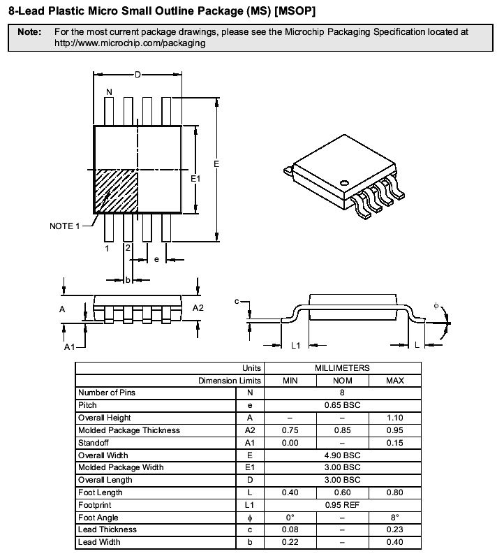
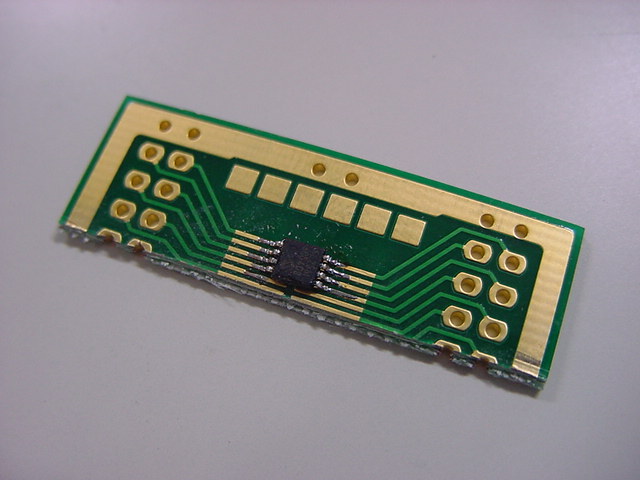
手元には40ピンDIPのPropellerチップが10個あるだけなので、 さっそく、ネット経由で部品を注文した。 ところが、シリアルEEPROMの 24LC256 については、この商社は、8ピンDIPを取り扱っていなくて、以下のMSOPというパッケージしかない。
ピン間は0.65ミリである。DIPの0.1インチの2.54mmとはだいぶ違う。 とりあえず、変換基板とレジストも注文してみた。 果たして、うまくハンダ付けできるだろうか。
2008年4月2日(水)
昨日の夕方、17:55にネットで注文したのに、もう今日の昼過ぎには部品が届いた。 さすが「電子部品のアスクル」、ちょっと高いけれども便利な商社である。
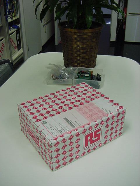

さて問題は、シリアルEEPROMの0.65ミリというMSOPパッケージと、それをDIPに変換する変換基板である。
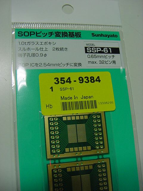
出して並べてみると---これは小さい(^_^;)。 鼻息で吹き飛んで床に落としたら、もう絶対に発見できそうもない。 これを付けられるだろうか。

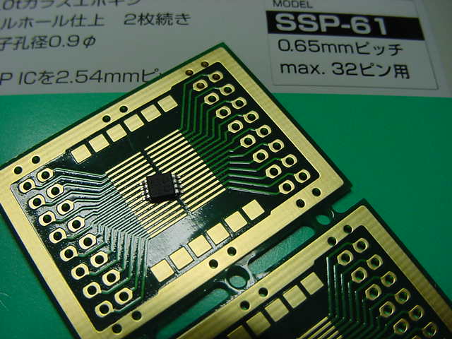
とりあえず、道具はいつものハンダ一式。 ただし必殺のツール、「フラックス」だけが頼りである。

そして、息を止めて集中すること数分間。 さすがにフラックスは素晴らしく、最初の挑戦からアッサリと綺麗にハンダ付け出来た(^_^)。 1枚の変換基板に多数のEEPROMを並べるのは次回にするとして、今回は変換基板をカットしてみた。 もちろん、残りの部分にもあと1個は取り付けできる。

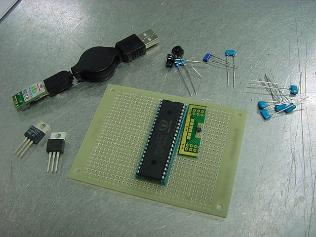
さて、それでは製作を進めよう---と部品を並べていて、5MHzの水晶振動子を注文し忘れていたことに気付いた。 仕方ないのでネットで注文して、これ以降の製作は、水晶が届く明日にすることにした。
ハードを離れて、Propellerツールに向かい、あらためてグラフィクス関係のライブラリを捜してみると、
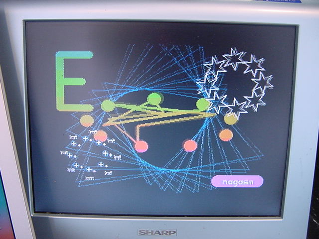
という一群の入ったディレクトリを発見した。 こういう場合には「demo」の名前がトップだ、ということで叩いてみると、 なんとビデオモニタにカラーグラフィックのアニメーションが現れた。 テキスト情報表示もいいけれど、これも欲しかったのである。 そして、PS2マウス対応だというMouse.spinはとりあえず不要であり、 TV.spinとGraphics.spinについては、ここまでのPropellerライブラリの傾向から、 おそらく既に調べたものと同一では、という気がした。 そこでとりあえず、
- Graphics_Demo.spin
- Mouse.spin
- TV.spin
- Graphics.spin
となるように整理してみた。 これはかなり簡単な作業であり、やはりE_TV02.spinとE_Graphics02.spinは、 TV.spinとGraphics.spinにそのまま置換できた。 以下はそのムービーである。
- ここまでの最新のexp022.spinはそのままに保留しておく
- Graphics_Demo.spinをコピーしてexp023.spinとリネームして改造
- exp023.spinからの参照はE_TV02.spinとE_Graphics02.spinとするように変更
- E_TV02.spinとE_Graphics02.spinは変更しない
- マウス処理をカット/コメントアウトする
- それでもグラフィックのデモが同様に行われる

そして、画面内では、文字列として定義した「Propeller」というテキストのグラフィック表示も実現していることから、 16進表示についてソフトウェア的に盛り込めば、exp022.spinから呼ばれていたE_TV_Terminal02.spinナシに、 直接にE_TV02.spinとE_Graphics02.spinを参照できることがわかった。
そこで、これまでに制作したMIDI関係とサウンド(サイン波)生成の機能のあるexp022.spinを、 ここでのexp023.spinに統合していくことを目指した。 MIDIの16進表示については、E_Numbers01.spinを使わないで表示することになる。
まずはMIDIの16進表示ナシで、単純に両者のプログラムを合体させたのが、 以下のexp024.spinである。 これで同様のグラフィックをライブ生成しながら、 MIDI入力・MIDI出力・オーディオ生成も同時に実行している。
{{ exp024.spin }}

CON
  _clkmode = xtal1 + pll16x
  _xinfreq = 5_000_000
  _stack = ($3000 + $3000 + 100) >> 2   'accomodate display memory and stack
  x_tiles = 16
  y_tiles = 12
  paramcount = 14
  bitmap_base = $2000
  display_base = $5000
  lines = 5
  thickness = 2

VAR
  long  tv_status     '0/1/2 = off/visible/invisible           read-only
  long  tv_enable     '0/? = off/on                            write-only
  long  tv_pins       '%ppmmm = pins                           write-only
  long  tv_mode       '%ccinp = chroma,interlace,ntsc/pal,swap write-only
  long  tv_screen     'pointer to screen (words)               write-only
  long  tv_colors     'pointer to colors (longs)               write-only
  long  tv_hc         'horizontal cells                        write-only
  long  tv_vc         'vertical cells                          write-only
  long  tv_hx         'horizontal cell expansion               write-only
  long  tv_vx         'vertical cell expansion                 write-only
  long  tv_ho         'horizontal offset                       write-only
  long  tv_vo         'vertical offset                         write-only
  long  tv_broadcast  'broadcast frequency (Hz)                write-only
  long  tv_auralcog   'aural fm cog                            write-only
  word  screen[x_tiles * y_tiles]
  long  colors[64]
  byte  x[lines]
  byte  y[lines]
  byte  xs[lines]
  byte  ys[lines]

OBJ
  midiIn : "MidiIn03"
  midiOut : "MidiOut01"
  audio : "AudioOut06"
  tv : "E_TV02"
  gr : "E_Graphics02"

PUB start | i, j, k, kk, dx, dy, pp, pq, rr, numx, numchr, dummy, para, p1

  'start tv
  longmove(@tv_status, @tvparams, paramcount)
  tv_screen := @screen
  tv_colors := @colors
  tv.start(@tv_status)

  'init colors
  repeat i from 0 to 63
    colors[i] := $00001010 * (i+4) & $F + $2B060C02

  'init tile screen
  repeat dx from 0 to tv_hc - 1
    repeat dy from 0 to tv_vc - 1
      screen[dy * tv_hc + dx] := display_base >> 6 + dy + dx * tv_vc + ((dy & $3F) << 10)

  'init bouncing lines
  i := 1001
  j := 123123
  k := 8776434
  repeat i from 0 to lines - 1
    x[i] := ?j // 64
    y[i] := k? // 48
    repeat until xs[i] := k? ~> 29
    repeat until ys[i] := ?j ~> 29

  'start and setup graphics
  gr.start
  gr.setup(16, 12, 128, 96, bitmap_base)

  'start MIDI/audio
  midiIn.start(7)
  midiOut.start(6)
  audio.start(10, 11)

  repeat

    'clear bitmap
    gr.clear

    'draw spinning triangles
    gr.colorwidth(3,0)
    repeat i from 1 to 8
      gr.vec(0, 0, (k & $7F) << 3 + i << 5, k << 6 + i << 8, @vecdef)

    'draw expanding pixel halo
    gr.colorwidth(1,k)
    gr.arc(0,0,80,30,-k<<5,$2000/9,9,0)

    'step bouncing lines
    repeat i from 0 to lines - 1
      if ||~x[i] > 60
        -xs[i]
      if ||~y[i] > 40
        -ys[i]
      x[i] += xs[i]
      y[i] += ys[i]

    'draw bouncing lines
    gr.colorwidth(1,thickness)
    gr.plot(~x[0], ~y[0])
    repeat i from 1 to lines - 1
      gr.line(~x[i],~y[i])
    gr.line(~x[0], ~y[0])

    'draw spinning stars and revolving crosshairs and dogs
    gr.colorwidth(2,0)
    repeat i from 0 to 7
      gr.vecarc(80,50,30,30,-(i<<10+k<<6),$40,-(k<<7),@vecdef2)
      gr.pixarc(-80,-40,30,30,i<<10+k<<6,0,@pixdef2)
      gr.pixarc(-80,-40,20,20,-(i<<10+k<<6),0,@pixdef)

    'draw small box with text
    gr.colorwidth(1,14)
    gr.box(60,-80,60,16)
    gr.textmode(1,1,6,5)
    gr.colorwidth(2,0)
    gr.text(90,-72,@pchip)

    'draw incrementing digit
    if not ++numx & 7
      numchr++
    if numchr < "0" or numchr > "9"
      numchr := "0"
    gr.textmode(8,8,6,5)
    gr.colorwidth(1,8)
    gr.text(-90,50,@numchr)

    'copy bitmap to display
    gr.copy(display_base)

    'increment counter that makes everything change
    k++

    dummy := midiIn.event
    if dummy <> -1
      midiOut.fifoset(dummy)
      if (dummy & $FF00FF) == $900064
        audio.change2(0)
        p1 := (dummy & $007F00) >> 8
        para := f_number[ (p1+4) // 12 ] >> ( (127-p1) / 12 )
        audio.change1(para)
      elseif (dummy & $FF00FF) == $900000
        audio.change2(7)
      elseif (dummy & $FFFF00) == $B00000
        para := dummy & $000007
        audio.change2(para)
      elseif (dummy & $FFFF00) == $B00100
        para := dummy & $000003

DAT
  f_number    long      1294309430,1371273070,1452813200,1539201960
              long      1630727660,1727695770,1830429900,1939272920
              long      2054588080,2176760240,2306197130,2443330740

tvparams                long    0               'status
                        long    1               'enable
                        long    %001_0101       'pins
                        long    %0000           'mode
                        long    0               'screen
                        long    0               'colors
                        long    x_tiles         'hc
                        long    y_tiles         'vc
                        long    10              'hx
                        long    1               'vx
                        long    0               'ho
                        long    0               'vo
                        long    0               'broadcast
                        long    0               'auralcog

vecdef                  word    $4000+$2000/3*0         'triangle
                        word    50
                        word    $8000+$2000/3*1+1
                        word    50
                        word    $8000+$2000/3*2-1
                        word    50
                        word    $8000+$2000/3*0
                        word    50
                        word    0

vecdef2                 word    $4000+$2000/12*0        'star
                        word    50
                        word    $8000+$2000/12*1
                        word    20
                        word    $8000+$2000/12*2
                        word    50
                        word    $8000+$2000/12*3
                        word    20
                        word    $8000+$2000/12*4
                        word    50
                        word    $8000+$2000/12*5
                        word    20
                        word    $8000+$2000/12*6
                        word    50
                        word    $8000+$2000/12*7
                        word    20
                        word    $8000+$2000/12*8
                        word    50
                        word    $8000+$2000/12*9
                        word    20
                        word    $8000+$2000/12*10
                        word    50
                        word    $8000+$2000/12*11
                        word    20
                        word    $8000+$2000/12*0
                        word    50
                        word    0

pixdef                  word                            'crosshair
                        byte    2,7,3,3
                        word    %%00333000,%%00000000
                        word    %%03020300,%%00000000
                        word    %%30020030,%%00000000
                        word    %%32222230,%%00000000
                        word    %%30020030,%%02000000
                        word    %%03020300,%%22200000
                        word    %%00333000,%%02000000

pixdef2                 word                            'dog
                        byte    1,4,0,3
                        word    %%20000022
                        word    %%02222222
                        word    %%02222200
                        word    %%02000200

pchip                   byte    "Propeller",0           'text
とりあえずここまで動けば、グラフィクスのパラメータをサウンドと同時に制御することで、 まさにマルチメディア・インスタレーションの入口に立ったことになる。 明日からが楽しみになってきた。
2008年4月3日(木)
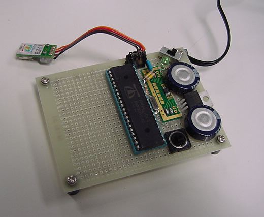
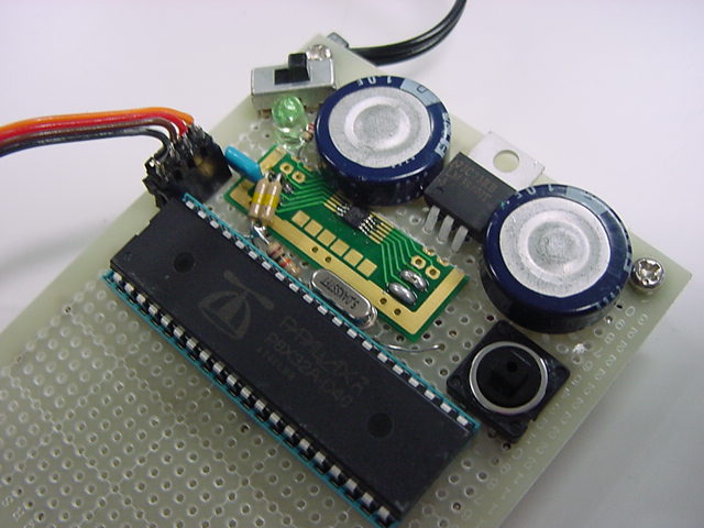
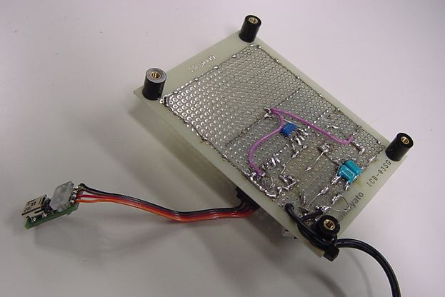
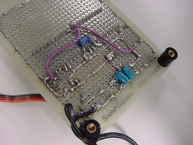
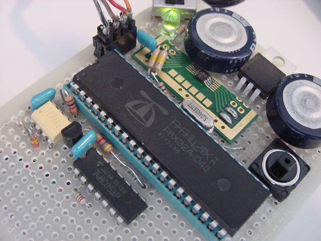
新学期の準備に追われているうちに午後になり、昨日注文していた水晶も届いた。 とりあえず、オリジナルのPropeller回路が動くかどうかまでは、作って実験してみよう。 まずは電源である。 マルツの小型スイッチングACアダプタの「+5V 2A」を使って、 +5Vラインは3端子レギュレータでなく直接、この出力が使えないか、試してみることにした。 +5Vを受けて3.3Vにしているのは、LM3940である。 パスコンは、参考回路図には「1000μF」とあったが、たまたま手元に「1F」という強烈なのがあったので、 これを+5Vと+3.3Vのラインに入れて、積層セラミックコンデンサの105をここにパラってみた。

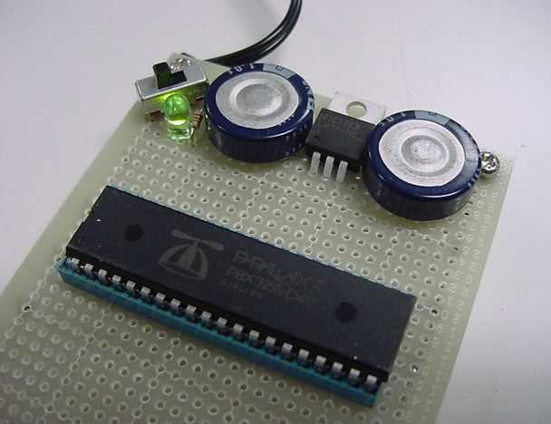
とりあえず電圧はちゃんと出たので、Propellerマニュアルにあった、 以下の回路図に従って、シリアルEEPROMとPropellerクリップを接続してみた。
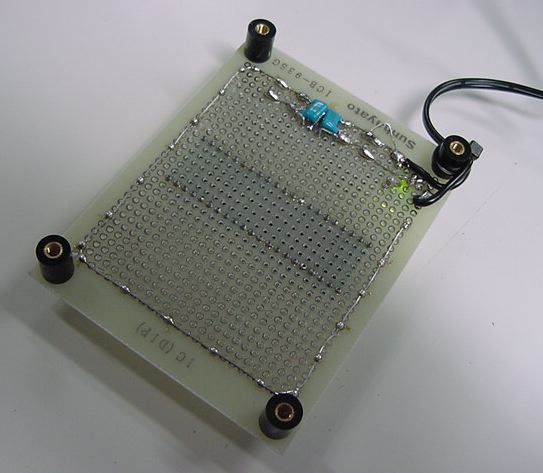
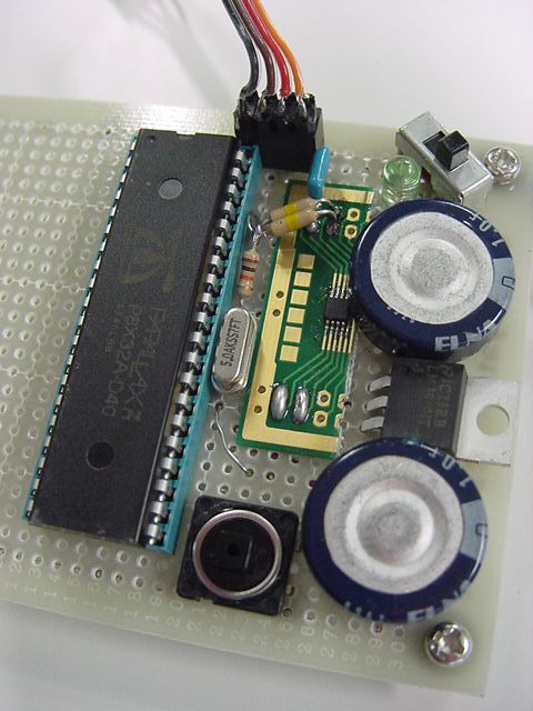
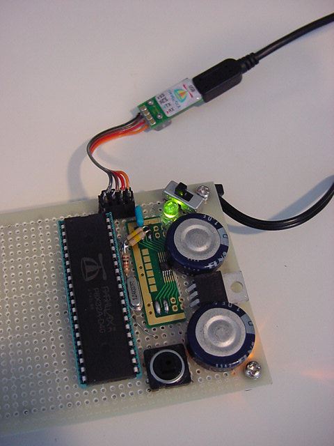
いつもは小さく感じるリセットスイッチが大きく感じるのは不思議だが、こんなカンジになった。
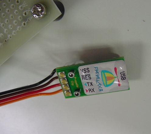
ここでとりあえず、パソコンPropeller Toolに移動して、 これまで使っていたPropeller Demo BoardからUSBケーブルを外して、 この試作基板に接続されたPropellerクリップに繋いでみた。 すると、WindowsはこちらにのPropellerクリップも、自動的に新しいハードウェアとして認識した。 そしてPropeller Toolのハードウェア認識メニューを走らせると、 以下のように、これまでのCOM4から新しいCOM5となって、無事に認識した。

Propeller Toolから、これまでに作ったプログラムをPropellerのRAMに転送するのも成功、 そしてVerifyチェックまである「EEPROMに転送」の実行もエラーなく成功した。 無事に、昨日の微細ハンダ付けのシリアルEEPROMは稼動しているようである。 あとはMIDI、オーディオ、ビデオのハードを作ればいいが、ちょっとビデオについては検討の余地があるので、 今日はここまで、とした。 自分でハンダ付けしたハードウェアが動くというのは、出来合いのDemoボードが当然のように動くのとはまた違って、 嬉しいものだ。
2008年4月4日(金)
トラ技の記事の製作例にするシステムについて考えてみた。 編集部の希望として、というのがあった。 またこちらからのメイルの中に
- Propellerの特長(処理能力)活かした製作記事
- 並列処理をハードウェアで行えることががPropellerの特長のひとつ
→そのような処理対象を製作テーマにできれば- あまり肩肘張った記事では読者から敬遠される
- 遊び心も多少含めて
若いエンジニアに「発想の転換CPU」「温故知新CPU」として紹介したい と書いたところ、 「記事中にコラムを設けて,1000字程度で触れるか、本文中にさりげなく含めて」 と、こちらも了解をもらった。 これを受けて編集部に提案したのは、
というテーマである。 AKI-H8やGAINERを使って、ホストPCにMax/MSP/jitterやFLASHやprocessingを使えば、 かなりのことが出来るのは当然として、 ここでは是非、「パソコン無しでソコソコの仕事をする」システムとしてみたい。 Propellerの8つのCogsがそれぞれの仕事をテキパキとこなして、 外界との関係性のアルゴリズムをspinでサクサクと作れる、 Propeller Toolによって、現場でもデバッグや改訂が出来る、 というあたりをアピールするのが目標である。
- 製作例として「インスタレーション」ということでいきたい
- 科学館などで体験できる、「不思議なビデオアート装置」みたいなイメージ
まだ「マイク入力」のサンプルプログラムと回路の実験をしていないが、 アナログの入力には1つのCogと2本の入出力ピンが必要なのは分かっている。 センサの入力はアナログであればこれと同等だし、 クロックタイプのセンサであれば、MIDI入力と同様にソフトウェアでモニタするので、 入力の1ピンだけで十分である。
これらをまとめて、とりあえず現状でのシステム構成要素として、 Propellerシステムを構成する機能ブロックを以下のように整理してみた。 これらを取捨選択してシステムを設計する、ということになる。
このような各要素に対して、Propeller全体としての制約条件は
- メイン処理
- Cog(0)を使用する
- プログラム用に入出力ピン4本を使用する
(P30/31 - ホスト、P28/29 - シリアルEEPROM)- ディジタル入力(スイッチ等)は直接にポートをモニタできる
- ディジタル出力(LED/リレー等)は直接にポートをドライブできる
- ビデオ出力のフレームレートごとの変化を担当
- MIDI入力FIFOをモニタしてイベントがあれば判定処理
- MIDI出力したい情報はMIDI出力FIFOに積んでおくだけ
- MIDI入力
- RS232Cなどシリアル入力でも同等
- 1個のCogを使用する
- 入力ピン1本を使用する
- 外付回路はフォトカプラとTR1個
- ソフトウェア的にMIDI信号をモニタして受信
- MIDIイベントFIFOに積んでMainがモニタする
- MIDI出力
- RS232Cなどシリアル出力でも同等
- 1個のCogを使用する
- 出力ピン1本を使用する
- 外付回路は74HC05を1個
- ソフトウェア的にMIDI信号を上げ下げする
- Mainが積んだMIDI送信FIFOから出力する
- サウンド出力
- 1個のCogを使用する
- 出力ピン2本を使用する→ステレオ(逆相)出力
- 外付回路はRCフィルタのみ
- Cog内部カウンタをPWMモードで使用する
- サンプリングは44.1KHz楽勝
- ソフトウェアでサウンド生成(シンセサイズ)できる
- 高精度のサイン波テーブル内蔵
- ビデオ出力(NTSC)
- 2個のCogを使用する(グラフィックドライバ/ビデオ信号スキャン)
- 出力ピン3本を使用する
- 出力ピンは [4n] [4n+1] [4n+2] の連続した3本であること
- 外付回路は3本の抵抗のみ→ミックスしてビデオ信号化
- ビデオチップもフレームメモリも不要で、ソフトウェアでビデオを生成
- ビデオ生成の詳細の解析はまだ(^_^;)
- アナログ入力
- 1個のCogを使用する
- 入力ピン2本を使用する
- 外付回路はRCのみ、外部A/Dは不要
- アナログ入力の詳細の解析はまだ(^_^;)
ということになる。 これまでに制作したインスタレーションなどの例であれば、 AKI-H8やI-CubeやGAINERの置き換え用途としては
- Cogは全部で8個まで
- 入出力ピンは全部で32本まで
ということになる。 これだと、センサ入力として1つのCogで複数のチャンネルを管理するのを別にして、 アナログ入力は5種類、ないし6種類の異なったタイプ(サンプリング周期、データ形態、 ソフトウェア後処理、等)を混在できそうである。
- MainのCog(0)
- MIDI入力
- MIDI出力
- アナログ入力(センサ用)
AKI-H8やI-CubeやGAINERでは困難な、 「パソコン無しのスタンドアロン」「ビデオ出力」「ステレオオーディオ出力」の機能を盛り込むとなると、 Propellerシステムの選択肢は俄然、増えてくることになる。 ここでは、欲張った場合にはピン数やCog数の制約から、 1つのPropellerで実現する制限が出て来るだろう。 ただしこれは、他の組み込みマイコンではちょっと手が届かない、贅沢な制約である。 例えば、
というようなシステムであれば、Cogは8個全部、 そしてセンサ入力に多数を使用しても、ピン数はなんとかなりそうである。 これをパソコン無しに実現し、マイコンシステムで悩む「割り込み」「マルチタスクモニタ」等が不要、 ということであれば、まさにPropellerの実力は鮮明になるだろう。 そこで今回のシステムとしては、このあたりを目指すことにした。
- MainのCog(0)
- (MIDI入力)(センサ用/デバッグ用)
- ビデオ出力[1]
- ビデオ出力[2]
- ディジタル入力(センサ用)
- アナログ入力(センサ用)
- ステレオオーディオ出力(リアルタイム・シンセサイザ)
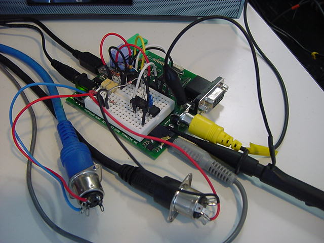
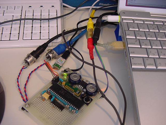
システムの方針が決まったので、試作基板の製作を続けることにした。 最終的には使わないとしても、せっかくオリジナル外付回路を作ったので、 MIDI INとMIDI OUTも製作し、目玉としてビデオ出力回路を2チャンネル、搭載することにした。 同時に2系統の異なる映像信号を生成するシステムというのは、パソコンでもなかなか大変だが、 Propellerであればもう1つのCogを映像生成に指定するだけの筈である。 オーディオはヘッドホンアンプでなく、ステレオミニジャックからのライン出力である。
まず最初に、Propeller Demo Boardのブレッドボード領域に製作した、 以下のMIDI IN回路とMIDI OUT回路とを、この新しい試作基板の上に作ってみた。
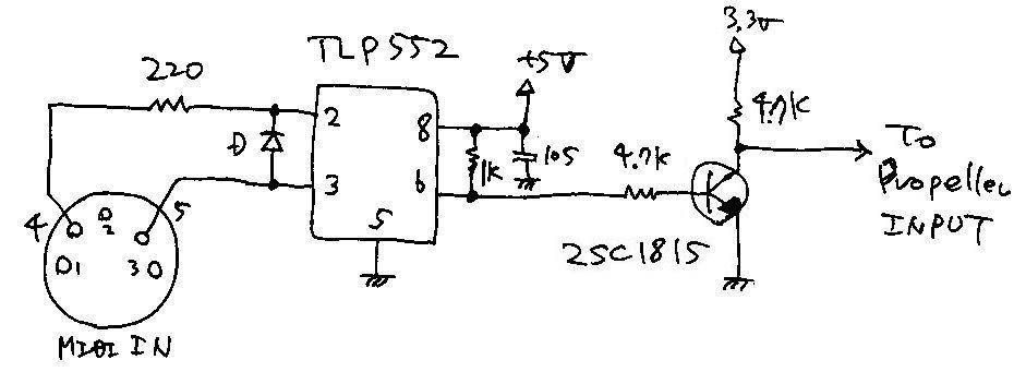
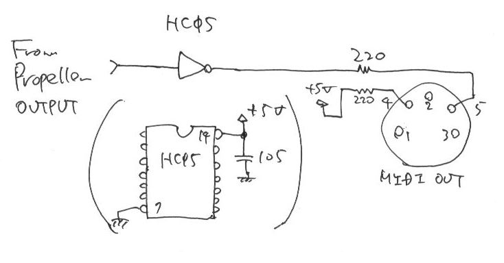
基板上ではこんなものである。
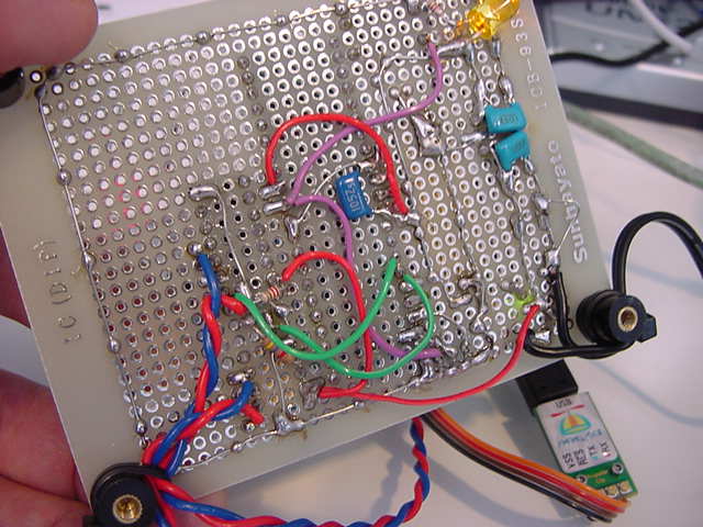
まずここまで作ったところで、Propeller Demo Boardと取り替えて、動作確認した。 ポートのピンの位置については、オーディオも含めて、以下のように定義した。
これに合わせて、ビデオも含めてポート(ピン)番号の定義がこれまでのPropeller Demo Boardと違ってくるので、 Topオブジェクトのファイル名については、新しい試作基板のものをまったく新しいものに変更した。 該当する変更部分は以下となる。
- P30/31 - ホスト接続用
- P28/29 - シリアルEEPROM用
- P27 - MIDI Input
- P26 - MIDI Output
- P24/25 - Audio出力(ステレオ)
OBJ
	midiIn : "MidiIn03"
	midiOut : "MidiOut01"
	v : "AudioOut06"

PUB Main | dummy, para, p1
	TV.Str(string("Audio_output_Cog ="))
	dummy := v.start(24,25)
	TV.Str(Num.ToStr(dummy, Num#DEC))
	TV.Str(string(", MIDI_input_Cog ="))
	dummy := midiIn.start(27)
	TV.Str(Num.ToStr(dummy, Num#DEC))
	TV.Str(string(", MIDI_output_Cog ="))
	dummy := midiOut.start(26)
	TV.Str(Num.ToStr(dummy, Num#DEC))
そして、以下のように無事にここまでは動いた。 まだビデオ出力は無いので、Max/MSPからMIDIを出して、 それがPropellerのソフトスルーでMIDIとして戻ることで確認した。
これに続いて、オーディオと、2系統のビデオ出力の回路を増設した。 オーディオは、とりあえずPropellerの出力から4.7KΩで受けて、GNDへは0.1μF、出力へは10μFで出した。 マニュアルとかのドキュメントによって、だいぶ数値のばらつきがあり、抵抗では10KΩと220Ωの両方の記事があった。 ビデオのピンの位置については、以下のように定義した。 片方をPropeller Demo Boardと同じにして、他のポートを8ビット単位で空けておくためである。
1.1KΩの抵抗が無かったので2.2KΩを並列にして、基板上ではこんなものである。
- P8/9/10 - ビデオ出力(A)
- P12/13/14 - ビデオ出力(B) - Propeller Demo Boardと同じ

ビデオ出力の片方をPropeller Demo Boardと同じにしたので、 同じプログラムで、とりあえずビデオ出力(B)は簡単に出てくれた。

あとはビデオ出力の基準(base)ピン番号を変えればビデオ出力(A)が出る---と思ったところで、ひっかかった。 Topオブジェクトからは、初期化の時に、明示的にビデオ出力のピン番号を指定していないのである。 ここで、リネームしたTopプログラムの proto001.spin と、ビデオ出力のために参照している E_TV02.spin との中から、関係していそうな部分を調べてみた。
proto001.spinの中で関係しそうなところは、
VAR
	long  tv_status, tv_enable, tv_pins, tv_mode, tv_screen
	long  tv_colors, tv_hc, tv_vc, tv_hx, tv_vx, tv_ho, tv_vo
	long  tv_broadcast, tv_auralcog
	word  screen[x_tiles * y_tiles]
	long  colors[64]
	byte  x[lines], y[lines], xs[lines], ys[lines]

PUB start | i, j, k, kk, dx, dy, pp, pq, rr, numx, numchr, dummy, para, p1, thickness
	'start tv
	longmove(@tv_status, @tvparams, paramcount)
	tv_screen := @screen
	tv_colors := @colors
	tv.start(@tv_status)
------

DAT
------
tvparams      long    0               'status
              long    1               'enable
              long    %001_0101       'pins
              long    %0000           'mode
              long    0               'screen
              long    0               'colors
              long    x_tiles         'hc
              long    y_tiles         'vc
              long    10              'hx
              long    1               'vx
              long    0               'ho
              long    0               'vo
              long    0               'broadcast
              long    0               'auralcog
あたりである。 初期化のtv.start(@tv_status)で渡すパラメータのポインタtvparamsには、 「pins」として「%001_0101」という謎の数値があった。 Propeller Demo BoardではP12-14がビデオ出力なので、 「12」すなわち「%1100」という文字列があれば、と期待したが、これは外れた。
そこでE_TV02.spinの中で関係しそうなところを調べると、
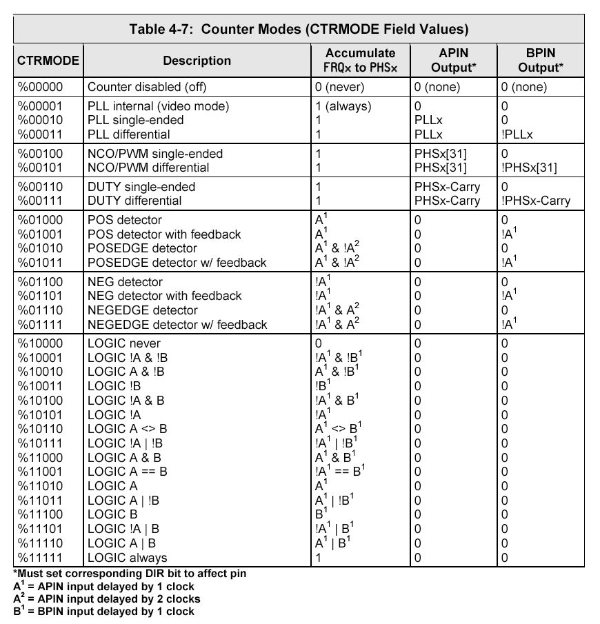
------
''VAR                   'TV parameters - 14 contiguous longs
''  long  tv_status     '0/1/2 = off/invisible/visible              read-only
''  long  tv_enable     '0/non-0 = off/on                           write-only
''  long  tv_pins       '%pppmmmm = pin group, pin group mode       write-only
''  long  tv_mode       '%tccip = tile,chroma,interlace,ntsc/pal    write-only
''  long  tv_screen     'pointer to screen (words)                  write-only
''  long  tv_colors     'pointer to colors (longs)                  write-only
''  long  tv_ht         'horizontal tiles                           write-only
''  long  tv_vt         'vertical tiles                             write-only
''  long  tv_hx         'horizontal tile expansion                  write-only
''  long  tv_vx         'vertical tile expansion                    write-only
''  long  tv_ho         'horizontal offset                          write-only
''  long  tv_vo         'vertical offset                            write-only
''  long  tv_broadcast  'broadcast frequency (Hz)                   write-only
''  long  tv_auralcog   'aural fm cog                               write-only
''The preceding VAR section may be copied into your code.
''After setting variables, do start(@tv_status) to start driver.
''All parameters are reloaded each superframe, allowing you to make live
''changes. To minimize flicker, correlate changes with tv_status.
''Experimentation may be required to optimize some parameters.
''Parameter descriptions:
------
''  tv_pins
''
''    bits 6..4 select pin group:
''      %000: pins 7..0
''      %001: pins 15..8
''      %010: pins 23..16
''      %011: pins 31..24
''      %100: pins 39..32
''      %101: pins 47..40
''      %110: pins 55..48
''      %111: pins 63..56
''
''    bits 3..0 select pin group mode:
''      %0000: %0000_0111    -                    baseband
''      %0001: %0000_0111    -                    broadcast
''      %0010: %0000_1111    -                    baseband + chroma
''      %0011: %0000_1111    -                    broadcast + aural
''      %0100: %0111_0000    broadcast            -
''      %0101: %0111_0000    baseband             -
''      %0110: %1111_0000    broadcast + aural    -
''      %0111: %1111_0000    baseband + chroma    -
''      %1000: %0111_0111    broadcast            baseband
''      %1001: %0111_0111    baseband             broadcast
''      %1010: %0111_1111    broadcast            baseband + chroma
''      %1011: %0111_1111    baseband             broadcast + aural
''      %1100: %1111_0111    broadcast + aural    baseband
''      %1101: %1111_0111    baseband + chroma    broadcast
''      %1110: %1111_1111    broadcast + aural    baseband + chroma
''      %1111: %1111_1111    baseband + chroma    broadcast + aural
''      -----------------------------------------------------------
''            active pins    top nibble           bottom nibble
''
''      the baseband signal nibble is arranged as:
''        bit 3: chroma signal for s-video (attach via 560-ohm resistor)
''        bits 2..0: baseband video (sum 270/560/1100-ohm resistors to form 75-ohm 1V signal)
''
''      the broadcast signal nibble is arranged as:
''        bit 3: aural subcarrier (sum 560-ohm resistor into network below)
''        bits 2..0: visual carrier (sum 270/560/1100-ohm resistors to form 75-ohm 1V signal)
これによれば、Propeller Demo BoardのP12-14では、 「%001_0101」というのは、ppp=%001、mmmm=%0101、ということになる。 確かに「pins 15..8」のグループなので、おそらくモードは「baseband」なのだろうと推定した。 さて問題は、ビデオ出力(A)では、同じ「pins 15..8」のグループで、上位4ビットでなくて、 下位41ビットに移動したいのである。 つまり、ppp=%001は同じ筈であり、mmmmをどこにするか、という事になる。
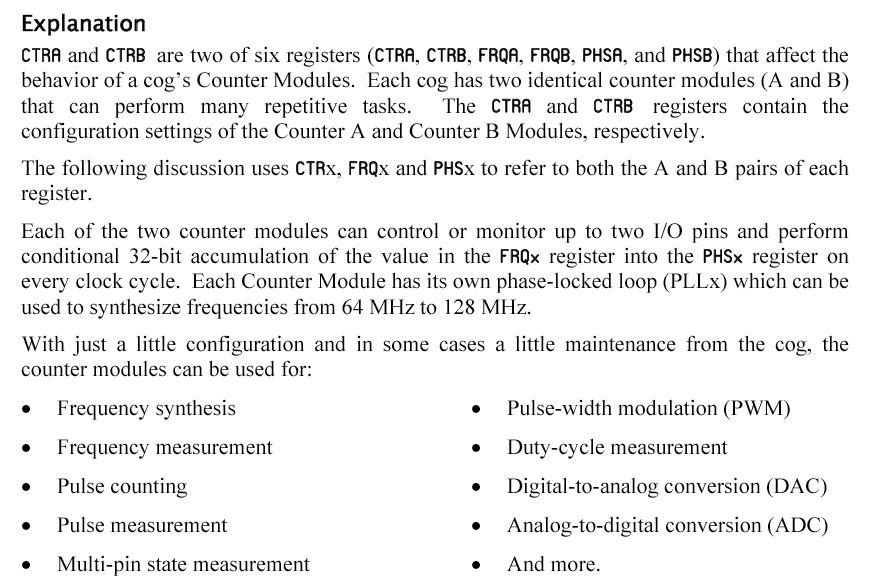
ここで、Propellerの データシート の中から、以下の部分を思い出した。

mmmmのビット3については、chroma signalやaural subcarrierのビットでここでは関係ないので、 同じグループの下位で「baseband」にするには、mmmm=0000であろう、と判断して、 proto001.spinのDAT領域の該当部分を「%001_0000」としてみた。 すると、一発でもう片方のビデオモニタから映像が出て、あっさり解決してしまった。 やはり、苦労してPropellerアセンブラのソースを読んできた甲斐があった。
ここで結論として、とりあえずproto001.spinのDAT領域の該当部分に設定する値は、
ということになった。 ただし、これでは排他的にしかビデオ信号が出ない。 PropellerのCogとして2系統を並列動作させる必要がある。 ちょっとトライした感じでは、Propeller Toolから「Run Time Error」が出て、単純に タスクをダブルで呼び出す---というカンジでは行かないようである。 いよいよ、難しいところに入ってきたのだろうか。
- ビデオ出力(A) - P8..10 = [001_0000]
- ビデオ出力(B) - P12..14=[001_0101]

Propeller Diary (5)