Theremin circuit diagrams
There are two ways to get yourself a theremin: buy one, or build one. If you can, the last option is an interesting one. You can choose between many versions, ranging from very simple to rather complex. Choose between transistors, tubes or integrated circuits. The advantage of building one is that you really get to know your theremin and can modify it until it works exactly the way you want. Below I list the diagrams I've found on the Internet. Some of them are available as kit, I will provide a link to the supplier in those cases. Please note: there are copyrights on most schematics. In most cases you can build your own theremin from the schematics below, but it's illegal to sell theremins or kits based on the diagrams below without permission from the authors. To build some of the more complex designs, you need to have some experience in electronics and rf technology, as well as some measurement equipment. Kits may require less experience and equipment. Enjoy!
I'm very pleased that I have to announce the following:
This page was getting too big. Therefore I have split the page up into a solid state theremin and a
Solid state theremins - only pitch control
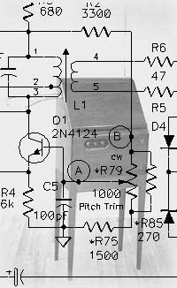
Wien bridge theremin
Diagram Rev.1(gif 13k)
This is a theremin with only a pitch control. It doesn't use any coils or hard
to find intergrated circuits. I think it's a good design in its class, worth
trying, it might even be a good base to experiment further (like adding volume
control). Arthur made some improvements in this revision-1 diagram.
This diagram is designed and ©2002 by Arthur Harrison. Look at
203 theremin
Diagram (gif 17k)
The 203 Theremin is a battery operated version of the Wien bridge theremin. It
is a pitch-only theremin. This design is a bit sensitive to interference, but
if that isn't an issue it may be a handy device for practice or demonstrations.
This diagram is designed and ©2001 by Arthur Harrison. Look at
Minimum theremin
Diagram (gif 12k)
Arthur Harrison designed the "Minimum Theremin" with the objectives of
simplicity and economy, and in response to frequent requests for an instrument
that can be built with readily available parts. This is a pitch-only instrument
that demonstrates the basic theremin concept, perfect for science fair projects
or as a coffee table conversation piece. Although it doesn't have the qualities
of more expensive and complex theremins, it is very inexpensive, relatively
easy to make, and sufficiently sensitive and stable for playing a melody.
This diagram is designed and ©1999 by Arthur Harrison. Look at
Simple theremin
circuit diagram (jpg 17k)
Another simple theremin. There is no volume control. Maybee nice to play with,
or to use for some sound effects. Source:
Very simple digital theremin
circuit diagram (gif 60k)
Very simple design with only 2 integrated circuits and a handfull of small
components. It has only pitch control, but is never the less a nice device to
play with. Design: C. R. Fischer, Hands On Electronics, Sept. 1987.
El Cheapo theremin
circuit diagram (gif 9k)
Very simple, and not so interesting, transistor theremin, only pitch control. I
don't know anything about the source of this design. You may
fill me in
on that if you know..
E.P.E. 1995 theremin
diagram (jpg 83k)
This is a transistor theremin published in
Modified E.P.E. 1995 theremin
diagram (gif 82k)
This is a transistor theremin originally published in
Popular Electronics Aug. 96 One Chip theremin
diagram (jpg 71k)
This artice has been referred to as the one-chip theremin while it's actually
called 'theremin on a chip'. It's a pitch-only design by Nick Cinquino.
RAES "classic theremin"
diagram (gif 6k)
This pitch-only theremin uses no LC circuits. Instead both oscillators are
build with 2 8038 function generator ic's. Followed by quite a nice mixer and a
LF356 audio amp. Designed by Dr. G. W. Raes.
Alexander Zeiliger's theremin
schematic diagram (gif 38k)
This is a scanned article about a transistor theremin by Alexander Zeiliger
(Sasha). It's a project paper, so the diagram is quite well documented. Now
with a new schematic diagram that's much better to read.
Solid state theremins - pitch and volume control
Elektuur (Elektor) optical 'theremin'
diagram (gif 10k)
This is an optical 'theremin' circuit. It does have both pitch and volume
control. Both are controlled by the amount of light that reaches the two LDR's
that are part of the circuit. It's a very simple design with only a few parts.
Elektuur (Elektor) 1973 theremin
diagram (gif 50k)
This design uses double mixing to avoid locking of the oscillators. That might be interesting if you want very low frequencies. The dual mixing makes the circuit rather complicated. Volume control is done optically with an LDR.
Analog theremin, Univ. of Glasgow
circuit diagram (gif 35k)
For this
analogue theremin
Digital theremin, Univ. of Glasgow
circuit diagram (gif 30k)
revised pitch-circuit diagram (GIF 17k)
The digital theremin uses CMOS oscillators and logic
gates to produce two DC Levels. One DC Level varies with
the proximity of the player's hands from the pitch
antenna, and the other DC Level varies when the volume
antenna is approached. This design of circuit is
advantageous because it pretty much depends on the
imagination of the constructer, what he/she wants to do
with these DC Levels. Obviously, a basic instrument would
have the DC Levels controlling a voltage-controlled
oscillator (VCO) and voltage-controlled amplifier (VCA).
However, such a DC Level could also control a voltage-controlled
filter (VCF). There are numerous designs of such voltage-controlled
circuit elements. In this circuit which you can download,
it shows a VCO and VCA block based on commonly available
commerical integrated circuits. Each block is controlled
by a CMOS oscillator/logic gate stage, of which there are
two (one for each antenna). The design has proven very
successful in recording, where the signal-to-noise is of
HI-FI quality, and also in playability, since the tuning
and volume offset is easily trimmed by adjustable knobs
on the front panel. The pitch control circuit has been revised and can easily
replace the original circuit. (Designed and built by Lindsay Reid
and Brendan Dougan for a
Electronics World (Moog) 1961 theremin
only diagram + partlist (112k gif)
In 1961 Dr. Robert Moog published one of the first transistorized theremin
designs. It was a popular design, as he sold over 1000 kits. Today this still
is a nice design for 'your first theremin'. You may need to consult a store,
specialized in radio components, for suitable coil replacements. Page 1-5 is
the full article, with interesting info on the circuit and on making the coils.
If you don't want to download all the large files, you could just download the
diagram with partlist. (All files taken from PDF files, send to me by Ted
Rosenberg -thanks :)
Moog Vanguard II 1964
power supply and amp (gif 57k)
pitch generator (gif 78k)
waveform generator (gif 47k)
envelope shaper (gif 48k)
This is nice. At the
Popular Electronics 1967 theremin
schematic diagram (18k gif)
diagram (35k pdf)
This is the design from Popular Electronics 1967. The PDF files
(Acrobat reader)
contain the full article, circuitboard and diagram + partlist. Its the
predecessor of the 1974 or SWTP #142 theremin. It's not wise to build this one
since the #142 theremin has some usefull corrections and modifications.
Popular Electronics 1974 / SWTP #142 Theremin
original circuit diagram (gif 25k)
Same design but different diagrams (©1999 by Athur Harrison), which are
easier to read:
part 1: volume section (gif 7k)
part 2: amplifier section (gif 7k)
part 3: pitch section (gif 8k)
This used to be a kit from Southwest Technical Products Corp. back in '74,
called kit #142. It was published in Popular Electronics in that year. The
design has some corrections and improvements over the '67 model. This theremin
is fairly easy to build, however, placement of the components is a bit
critical. Look at
#144 Theremin
part 1: volume section (gif 9k)
part 2: amplifier section (gif 11k)
part 3: pitch section (gif 9k)
Some improvements were made on the #142 theremin. The result is, considering
its simplicity, a good instrument, with a clean sound. Today it's still a
design worth building. However, since RF technology is involved (like with all
theremins) component placement is somewhat critical. More info and
construction details can be found at
#145 Theremin
diagram (gif 39k)
In nov. 2000 Athur Harrison supprised us with a new redesign of the #144
theremin. This new design promisses to be more stable thanks to a new
oscillator design (differential paired instead of Colpitts). And changes have
been made to the oscillator levels, reducing non-linear distortion. The result
is a consistent sound troughout the entire volume range. Also, there is less rf
noise on the audio output thanks to an added filter. A full description of the
circuit and detailed construction instructions can be found at
PAiA Theremax kit
Electronics Now feb/mar 1996
circuit diagram (gif 47k)
circuit board (gif 76k)
component placement (gif 280k)
Big Briar (Moog) Etherwave
a.k.a. Electronic Musician 96 theremin
circuit diagram (gif 47k)
This is a truly professional theremin, designed by Robert Moog. It's sold by
Silicon Chip August 2000 theremin
circuit diagram (gif 74k)
circuit board (gif 101k)
placement (gif 78k)
A fairly simple but nice design from the Australian Magazine
Other gesture controllers
Controller 0-5V outp.
circuit diagram (jpg 13k)
This diagram contains the obvious two oscillators and mixer, followed by a
intergrating circuit that produces 0-5V output. Its probably derived from the digital theremin diagram above. This is a great diagram for
building your own gesture controller(s). It could be connected to an analog
synth or whatever you can dream up. Imagine a 3d setup, controlling pitch,
volume and waveshape.. Source: